
Show Your Quarry Conveyor Impact Rollers Supplier Where the Rock Lands

A replacement impact roller cannot protect the belt where the incoming rock misses its support. A contractor choosing a quarry conveyor impact rollers supplier should show where the material lands, how the belt is supported there and where the loading zone changes into normal carrying support. GRAM’s rubber-ring impact rollers and load-zone belt support provide two routes to assess. Begin with the actual chute and belt position before specifying a roller diameter or replacement quantity.
The buyers who benefit most are quarry maintenance teams and contractors altering crusher discharge or transfer chutes. First confirm the material stream under credible operating conditions, including its position across the belt. Then give the supplier the existing station geometry and shaft interfaces. The product name does not establish an impact capacity or prove that the support is correctly located.
A quarry conveyor impact rollers supplier needs the rock landing position
The material trajectory and the support station are parts of one loading arrangement. Identify the belt direction, chute outlet and landing region on a drawing. Record any difference between an empty-belt position and the loaded operating condition using the plant’s approved engineering assessment. The supplier should not have to infer these relationships from an isolated roller sample.
Crusher discharge changes can move the impact away from the original station
A quarry modifying a crusher discharge may retain the original conveyor frames. If the rock now enters at a different position or with a changed stream shape, those frames may no longer place the support beneath the relevant landing region. Review the modified transfer as a system. Copying the old roller dimensions is a mounting decision, not an assessment of the new impact condition.
Provide the range of stone sizes and the intended feed condition to the responsible designer. Describe whether large fragments occur regularly or during an upset. The supplier needs that operating basis to discuss the offered assembly. No drop height, impact energy or load rating should be invented from a general photograph of the product.
Edge loading should be distinguished from central belt support
A buyer seeing belt-edge damage should identify where the material actually lands and how the edge is supported. The issue may involve the stream location, chute geometry or surrounding contact rather than the roller material alone. Do not assume every edge mark means the plant requires impact rollers along the entire conveyor.
Have the belt and transfer inspected under the approved isolation procedure. Describe the damage position without claiming a cause that has not been established. A drawing and photographs of the isolated arrangement can help the supplier understand the interface, while the plant’s engineer determines the required support and any transfer correction.
Quarry impact roller selection must define the rubber-ring assembly
GRAM’s impact roller construction uses rubber rings on the working body. That is a different contact surface from an ordinary steel carrying roller. Identify the offered complete assembly, including the working body, bearing ends and shaft interfaces. A rubber roller enquiry should specify that impact-support function rather than leave the supplier to choose between ringed and continuously coated products.
Rubber rings should be reviewed with the supported belt shape
The ringed surface belongs to the loading-zone support arrangement. Ask how the proposed roller fits the intended station geometry and where it contacts the belt. If an existing sample is worn, compare the offered new arrangement with the approved conveyor drawing rather than copying worn dimensions without review.
The rubber-ring impact roller discussion explains that construction boundary. For a quarry enquiry, keep the principal question focused on the rock landing zone and support transition. Ring dimensions alone cannot determine whether the assembly is located correctly beneath the transfer.
Shaft ends still need to fit the retained quarry brackets
Record the actual mounting span and shaft end form. If the supplier proposes a different end assembly, compare its full envelope with the frame and neighboring components. A matching nominal roller length does not establish that the shaft seats or bearing ends fit without interference.
Where the repair retains the station brackets, inspect those interfaces before ordering. Damage or distortion in the retained frame can affect the installed support position. Do not use a different roller dimension to compensate for an unreviewed frame problem. Have the equipment owner resolve the mounting condition first.

Compare rubber-ring rollers and impact beds at the actual transfer
GRAM’s load-zone support images show longitudinal bars and inclined side regions. This is a different support arrangement from rotating impact rollers. The choice should be evaluated against the conveyor geometry, material entry and maintenance needs. It is not enough to select whichever product appears more substantial in a photograph.
A contractor may need to assess how the proposed support affects the belt contact region and the surrounding loading arrangement. Provide the retained equipment envelope and the approved support requirement. Any dimensional or operating suitability of the offered bed must be established for that project; the general product route does not declare a universal impact rating.
Replacement access differs as well. A roller needs a defined removal path from its brackets, while a bar-type support needs its own access arrangement. Include guards and nearby chute components in the review. The plant should not discover that the selected replacement cannot be serviced through its approved maintenance route after installation.
The quarry loading zone needs a clear exit into carrying support
Impact support is not the whole conveyor. GRAM’s steel carrying roller route is relevant beyond the loading zone, while its suspended garland range offers another carrying arrangement for bulk materials. Each assembly has its own mounting and support geometry.
Show where the belt leaves the proposed loading support and reaches the next carrying station. Have the designer assess that transition against the belt and load conditions. A support arrangement can be appropriate at the landing point while still needing a coordinated transition to the surrounding stations.
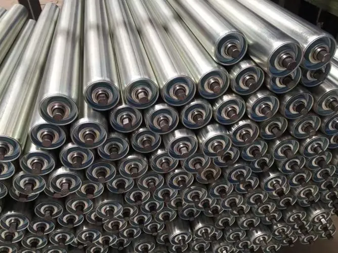
GRAM’s main roller range provides the broader construction choices. Use it to identify an appropriate carrying or replacement route after the support function is established. Do not treat every roller on a quarry line as an impact roller simply because the first transfer handles falling stone.
External Rulmeca bulk component information distinguishes impact and carrying products. That functional distinction supports the transfer review. Its product-specific capacities, models and installation dimensions are not ratings for GRAM equipment.
Include oversize rock and fines in the quarry impact offer
Oversize rock and fine aggregate should both appear in the transfer description
A quarry’s usual product description may omit the occasional large fragment that matters at a loading zone. Tell the responsible designer which operating conditions can produce that fragment and how the feed is controlled. The supplier’s assembly proposal should refer to the defined range. An impact rating cannot be chosen from the average material description alone.
Fine material can create another issue around the same station: deposits at end components or the retained brackets. Describe those conditions separately from the rock impact. A rubber-ring working surface addresses the support construction, while contamination at the ends requires a discussion of the offered bearing protection and maintenance exposure. One feature should not be presented as resolving both automatically.
For a chute modification, show the proposed and retained geometry clearly. If the station location, loading direction or adjacent support has changed, identify who approves that change. The roller manufacturer can supply against a defined assembly requirement, but the quarry’s transfer design must be coordinated by the responsible project team.
A buyer planning a phased repair should identify which parts will remain in service after the new impact assembly is fitted. Worn neighboring carrying rollers, damaged brackets or unresolved belt contact can affect the installation. Inspect and assess those retained interfaces through the approved procedure rather than assuming a new loading-zone product makes the surrounding equipment acceptable.
If several transfers need replacements, keep each loading description attached to its station identification. Two stations can use similar roller dimensions while receiving different rock streams. The supplier should know whether the buyer has established a common duty or simply has a convenient common frame size. That distinction prevents an unreviewed substitution between transfer locations.
Ask the supplier to identify the assembly offered for the stated landing condition and mounting arrangement. If an applicable load or impact performance is required, obtain the corresponding product-specific information and test basis. A generic heavy-duty description cannot establish the value needed for the plant’s engineering approval.
Inspect delivered rubber rings, end components and shaft interfaces against the approved assembly record. Check visible damage and rotation before installation. Where a set contains different positions or components, preserve their identification. An undocumented change in working profile or mounting geometry should be reviewed before it enters the loading zone.
Agree packing that protects the rubber working surfaces and keeps projecting shaft ends from damaging neighboring components. Mark the replacement packages by station or transfer position. If ordinary carrying rollers arrive in the same delivery, keep them distinct from the ringed impact assemblies.
Show the supplier the rock path before approving the impact roller order. The useful replacement is the one that matches the defined support geometry at the actual landing zone and connects properly to the carrying arrangement beyond it. If the rock path has changed, resolve that change rather than expecting a stronger-sounding roller description to compensate.
Last Updated on October 3, 2026 by gramconveyor_admin


