
Before a Custom Conveyor Rollers Manufacturer Cuts the Tube, Agree Which Dimensions Locate the Roller
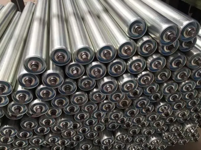
A drawing marked “roller length” can refer to the tube, the working face, the full assembly or the shaft. Those are not automatically the same dimension. Before a custom conveyor rollers manufacturer starts production, agree which surfaces locate the roller in the machine. GRAM’s roller offering includes fabrication to customer specifications; engineering buyers and equipment builders should supply an unambiguous assembly definition, then compare the steel, polymer, nylon or impact route against it. A single length written beside a photograph is a weak basis for approving a custom component.
A custom conveyor rollers manufacturer needs to know where the dimension starts
Identify the actual dimension being requested and its endpoints. If the customer gives only a number and the word length, the supplier may interpret a different part of the assembly from the designer. Resolve that ambiguity before pricing or manufacturing instead of expect the receiving team to recognize it after the components arrive.
Tube length is not necessarily the usable roller face
The rotating body can have end regions or additional working-surface elements that make a simple tube measurement insufficient. Show the required belt-contact region in the assembly drawing. A measurement of the body should not be presented as a complete definition of the working face unless the intended construction makes that relationship clear.
For a contractor replacing components in retained brackets, the removed roller can help explain the existing arrangement. Keep its measured condition separate from the requested new geometry. A body damaged or worn at one end does not provide an unquestionable reference for the original face dimension.
- Body or tube dimension
- The specified endpoints on the rotating body; identify exactly which surfaces the drawing uses.
- Shaft projection and end geometry
- The portions outside the rotating body and the particular interfaces that meet the retained brackets.
- Installed support span
- The separation of the shaft support locations in the actual machine, not an alternative name for body length.
- Complete assembly envelope
- The outer extent of all relevant supplied parts, which may include projecting ends or a ringed working surface.
Steel roller bearing ends belong in the assembly drawing
GRAM’s steel assemblies show bearing ends and projecting shafts beside their cylindrical bodies. The custom order should identify the required end arrangement with the body. A dimensioned tube does not tell the manufacturer all the interfaces needed to install and support the complete roller.
The bracket locates the shaft, not a loose tube on a bench
Show the retained support surfaces and the required shaft interfaces. The designer should determine which dimensions control placement in those supports. Avoid a drawing that gives a complete outer length while leaving the shaft ends undefined; a component can satisfy that outer envelope yet fail to sit correctly in the retained brackets.
The same principle applies when the two ends differ. Identify each end rather than assume a symmetrical assembly. A site photograph can suggest that one end has a different projection, but it does not define the geometry or its acceptance tolerance. The approved drawing must answer that question.
If the supplier proposes an end construction different from the one requested, have the responsible designer review the change. An attractive body price should not obscure the fact that the alternative shifts a locating surface or changes the way the shaft is retained. The purchasing line should reference the accepted complete assembly.
Bearing location must remain connected to the supported shaft
The bearing arrangement and shaft support geometry are connected parts of the roller. Identify the offered arrangement and the applicable assembly information instead of selecting a bearing name separately and assume it completes the drawing. A bearing description cannot establish the installed load path on its own.
This article does not prescribe bearing fits or shaft tolerances. Those require the actual components, intended duty and responsible design acceptance. The buyer’s useful action is to make sure the manufacturer and designer are discussing the same interfaces, not apply a universal tolerance copied from an unrelated roller.
A polymer substitution can preserve one dimension while changing another
GRAM’s polymer route describes a polymer body with precision bearings, non-contact rubber sealing and metal end caps. That arrangement should be evaluated as a complete component. Matching a steel roller’s body length does not prove that every end surface and supported position remains identical.

Preserve the required interface, not an assumed internal construction
An equipment builder may want a polymer alternative while retaining its existing frame. Give the supplier the machine interfaces that must remain compatible and let the proposed complete assembly be reviewed against them. Do not force an undocumented internal arrangement from the old steel component onto a different construction merely because its exterior looks similar.
Conversely, a material substitution should not be permission to alter the installed support position without disclosure. The drawing should make the retained interfaces visible so a reviewer can identify which changes affect fit and which concern the construction inside the assembly. Keep both kinds of change explicit in the proposal.
The nylon roller route is another product family to review where appropriate. Its name does not establish a particular manufactured dimensional tolerance or make it identical to every polymer roller. The manufacturer should identify the proposed material and complete geometry for this order.
Rubber-ring impact rollers need a working-surface dimension
GRAM’s impact assemblies have a rubber-ring working surface. The outside of those rings, rather than only the underlying body, meets the belt. A custom impact-roller drawing should therefore identify the complete contact profile with its mounting interfaces.

The ringed diameter belongs beside the supported belt line
If the designer requires a particular belt support geometry, the drawing needs the accepted outside profile and the shaft position that establishes it. A matching tube diameter does not ensure a matching ringed diameter. Equally, a matching ringed diameter does not define the shaft interfaces that place it correctly in the station.
Specify the intended ring arrangement through the approved construction information. A photograph is not enough to establish spacing or an acceptable compound. The order should distinguish the required geometry from the performance evidence needed for the intended impact duty; neither can be inferred from the other.
Custom roller acceptance should use the drawing’s own measurement references
Decide which dimensions the receiving team must verify against the accepted drawing. Name the reference surfaces and the condition in which each measurement is meaningful. A measurement made across different endpoints cannot demonstrate conformity to a drawing dimension merely because it gives a familiar number.
Define the measurement before choosing the tolerance
The responsible designer should determine the required tolerance and the applicable method. The buyer should first make the dimension itself understandable: which feature, which reference and which assembly condition. Debating a tight numerical tolerance for an ambiguously named overall length does not improve the drawing.
For relevant custom assemblies, the parties may also need an agreed way to assess the working surface or rotation. Keep those criteria tied to the intended roller and duty. Do not make an unsupported runout claim or universal balance requirement just to make the supplier evaluation appear more technical.
Professional suppliers make complete component drawings available; Rulmeca’s drawing portal illustrates that approach, while its technical resource centre separates component scopes. These are industry references. Their dimensions, models and acceptance limits must not be transferred to a GRAM custom order.
Do not replace a functional locating reference with a convenient body edge
A body edge may be easy to measure on a bench without being the surface that locates the roller in service. Show the functional reference selected by the designer and keep dimensions related to it clearly distinguishable. The drawing should explain which features establish position, not leave the inspector to choose whichever edge is most convenient.
Where an end cap or ring extends beyond the underlying body, identify that extension separately. A complete envelope measurement and a body measurement can both be useful, but they answer different questions. Labeling both as roller length invites a disagreement that tighter tolerances cannot resolve.
For an assembly with several dimensioned features between its locating surfaces, ask the designer to identify how conformity to the installed requirement will be judged. The manufacturer should not have to infer which independently specified dimension takes precedence if they appear inconsistent. Resolve the drawing question before production instead of ask the receiving team to decide which conflicting dimension it should waive.
The approved roller revision should be the one that reaches production
Once the required dimensions are clear, identify the approved drawing revision in the final order. If a supplier proposes a different end construction during price negotiation, revise the accepted information before release. Otherwise the workshop can manufacture one interpretation while the receiving team checks another.
Ask the manufacturer to identify unresolved drawing questions before cutting or assembly. This is especially useful when the drawing comes from an old component and not every original detail is available. Leaving an uncertain dimension open for approval is preferable to presenting a guessed feature as a confirmed requirement.
Handling protection should preserve the accepted shaft ends and working surfaces, with the drawing identity retained on the supplied units or agreed package. A custom shaft projection damaged in transit can undermine the interface the order was designed to preserve. Packaging protection is therefore related to the particular assembly, rather than an unrelated request for “good export packing.”
The existing custom roller overview describes the broader product route. For this order, the decisive step is narrower: approve a complete drawing whose dimensions locate the roller in the actual machine. Compare price after the endpoints, interfaces and acceptance references mean the same thing to the designer, manufacturer and receiving team.
Last Updated on October 3, 2026 by gramconveyor_admin


