
Load Position Changes the Order You Send a Steel Conveyor Rollers Manufacturer
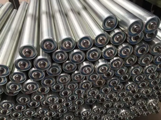
Where does the load sit along the roller face? A steel conveyor rollers manufacturer needs that answer before a long roller is treated as an approved heavy-load replacement. The diameter and material name describe only part of the component. For an engineer retaining the conveyor supports, start with GRAM’s steel roller range and identify the face length, shaft support positions, load distribution and operating duty of the complete proposed assembly. Those particulars belong on the same approval record.
A broad material load, a concentrated contact and a changing distribution are different conditions for a roller. The buyer should describe which one the conveyor presents. Asking for a stronger steel roller without identifying that condition can produce proposals that appear comparable on price while answering different mechanical questions.
Give the Steel Conveyor Rollers Manufacturer the Load Position Along the Face
GRAM describes steel roller bodies rotating around a central axle for industrial material handling. The assembly must carry its load through the body, bearings and shaft supports. The location and distribution of that load therefore matter alongside its magnitude. A material label cannot establish the capacity of an unnamed assembly.
A Long Steel Roller Face Does Not Describe the Shaft Support Span
The working face and the distance between the shaft supports are different measurements. Identify both. A proposal for a longer body may retain a shaft arrangement, change the supports or require a revised frame. The engineer needs to know which condition the offered roller assumes.
Consider a buyer extending the useful supported width while retaining the existing brackets. The new roller should not be selected solely because its face reaches the requested length. The complete geometry and proposed load must be assessed against the actual support positions. If the supplier assumes different supports, that assumption must become an explicit project change.
The relevant drawing should show where the load acts in relation to the bearing and support positions. A few unrelated dimensions on photographs can leave that relationship unclear. Use a common reference so the shell, shaft and load case can be reviewed as one assembly rather than as separate component sizes.
Concentrated Contact Needs a Different Description from Distributed Material
A conveyor carrying material broadly across a belt presents a different load description from a localised contact. The purchasing team should identify the distribution the engineer is expected to assess. Do not convert the total carried load into a roller capacity by dividing it between components without an appropriate system calculation.
For an unevenly loaded bulk conveyor, record whether material consistently favours one part of the belt and whether that distribution changes. The proposal should account for the intended operating conditions, including relevant loading variations. A central load drawn for convenience does not describe every operating case.
For a return-belt roller, describe accumulated material separately from the cleaned belt contact; it can alter the operating condition.
If the buyer is uncertain about the load allocation to a particular roller, keep that as an engineering question. A supplier cannot resolve it from outside diameter alone. The requirement should state the system information available and identify which load assessment is needed before the component is approved.
A second purchase situation arises when a roller face is lengthened to support a wider material path but the load remains concentrated toward an old transfer position. The resulting duty is not necessarily a uniformly loaded longer roller. Show the unchanged loading position within the revised face outline so the manufacturer does not assess an assumed distribution that the conveyor will not present.
Where material buildup changes the contact or loading condition, describe that operating variation separately from the clean condition. The supplier should know which condition the project expects the proposed assembly to accommodate. Do not use a photograph taken after cleaning as the only evidence for a roller that routinely operates with a different material distribution.
Review the Steel Roller Body and Shaft as One Proposed Assembly
A thicker-looking body or a larger shaft may influence the proposal, but neither is a complete rating. The selected construction must be assessed for its duty and installation. GRAM’s conveyor roller families help identify different routes; approval belongs to the actual offered roller, including its bearings and ends.
Shell Condition and Shaft Condition Should Not Be Combined into One Failure Label
A plant engineer examining an old roller may find damage to the working surface, persistent deformation or poor rotation. Those observations should remain separate. Surface wear does not automatically prove that the shaft is undersized, and poor rotation does not automatically require a thicker shell.
Record where deformation or wear appears along the face. Compare that location with the known loading pattern and support arrangement. If the visible problem is concentrated near one end, a photograph of the middle of the roller may miss the evidence most relevant to the replacement decision.
Where a shaft or bracket has changed position, establish the intended geometry before copying the damaged component. A replacement drawing based on a bent assembly can reproduce the wrong condition. Separate measurements of the serviceable retained frame from measurements of the failed roller.
If two steel proposals use the same outside diameter, compare their offered construction and stated assumptions before comparing their prices. Identify the shell description, shaft arrangement, bearing construction and supported span each bidder has evaluated. A diameter match does not reveal whether the assemblies were assessed against the same load position.
When a manufacturer supplies a load acceptance statement, retain the drawing revision and operating condition to which it applies. If the face length or shaft support arrangement changes later, ask for an updated assessment of that revised assembly. A statement for the earlier construction should not remain attached to a commercially amended roller with different mechanical geometry.
Metso’s heavy-duty roller technical material treats the roller as a construction with bearing and sealing features. Its ratings belong to Metso. The useful comparison principle is to evaluate a complete assembly for a defined duty rather than assign capacity from a shell description.
Roller-end Geometry Must Preserve the Intended Support Relationship
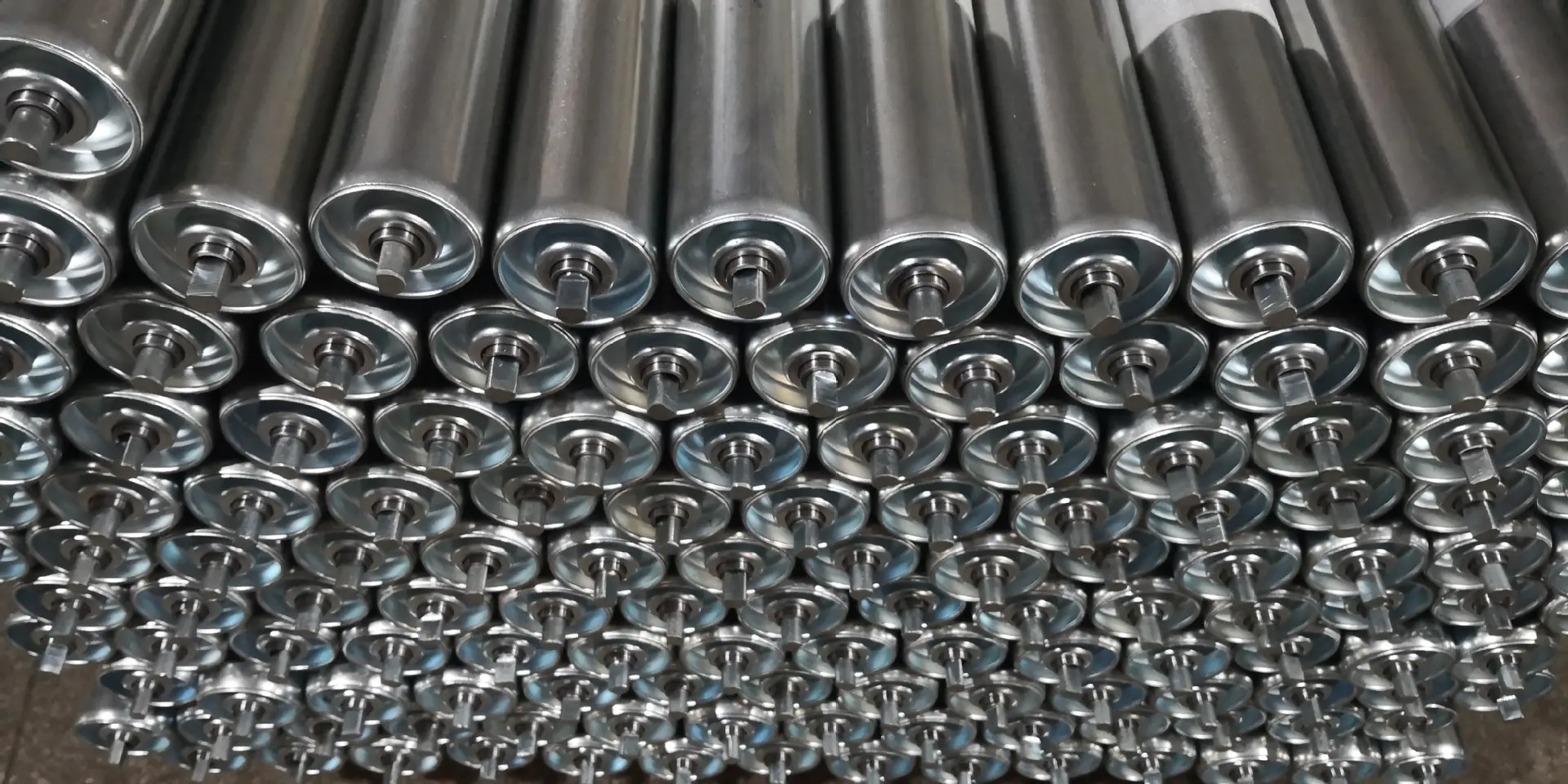
Identify how the shaft ends locate in the retained frame and how they are secured. The end form and supported span should agree with the proposed assembly drawing. A roller with an acceptable body length can still have a shaft arrangement that changes how the load reaches the conveyor structure.
If the proposal changes an end feature, establish whether the retained bracket is still suitable. Do not resolve a dimensional disagreement with an improvised mounting change unless that change has been assessed. The approval needs the actual installed arrangement, not an assumption that the installer will make the component fit.
Steel Roller Bearings Need the Actual Rotation and Contamination Duty
The bearings support rotation under the proposed load. Identify belt speed, roller dimensions and the conditions around the roller ends so the supplier can assess the offered assembly. A buyer should not compare two bearing descriptions while omitting the operating duty that makes those descriptions meaningful.
A Sound Steel Surface Can Conceal a Bearing-led Replacement Problem
If a roller body remains visibly intact but no longer turns as intended, examine the bearing and contamination condition. Buying a thicker tube alone may leave the original failure route unchanged. Describe water, dust, splash or cleaning exposure where those conditions reach the assembly.
A maintenance buyer may observe repeated rotation failures beneath one transfer area but few elsewhere. Keep that location information with the order. It can indicate why a bearing or sealing review is needed for that position instead of an undifferentiated request to replace every roller with a heavier shell.
Do not infer a bearing service life or an environmental rating from a smooth hand-rotation check. That check can contribute to a receiving inspection, but it does not establish performance under the conveyor load and speed. Request the construction-specific information required by the project’s acceptance agreement.
Steel and Polymer Roller Proposals Need the Same Defined Load Case
GRAM’s polymer rollers are described with a machined tube or solid bar, sealed precision bearings, non-contact rubber seals and metal end caps. That is a separate assembly route to review where the application warrants it. It does not make a polymer body an automatic substitute for a specified steel roller.
Compare steel and polymer proposals against the same face geometry, supported span, load distribution and exposure. Otherwise the comparison can attribute a difference to material while the offered assemblies actually have different construction assumptions. Keep body material and complete mechanical suitability as related but separate decisions.
Separate Impact and Suspended Roller Duties from Plain Steel Carrying Duty
Some positions require more than a change to steel shell dimensions. GRAM’s rubber-ring impact rollers and linked carrying garlands illustrate two different support routes. The engineer should identify which function the replacement must perform before comparing roller bodies.
At a loading point, the material contact and support arrangement need assessment together. A plain steel carrying roller should not be offered as an equivalent to a ringed impact assembly merely because it appears robust. The rubber-ring construction has a different contact function, and the complete station must suit the actual loading duty.
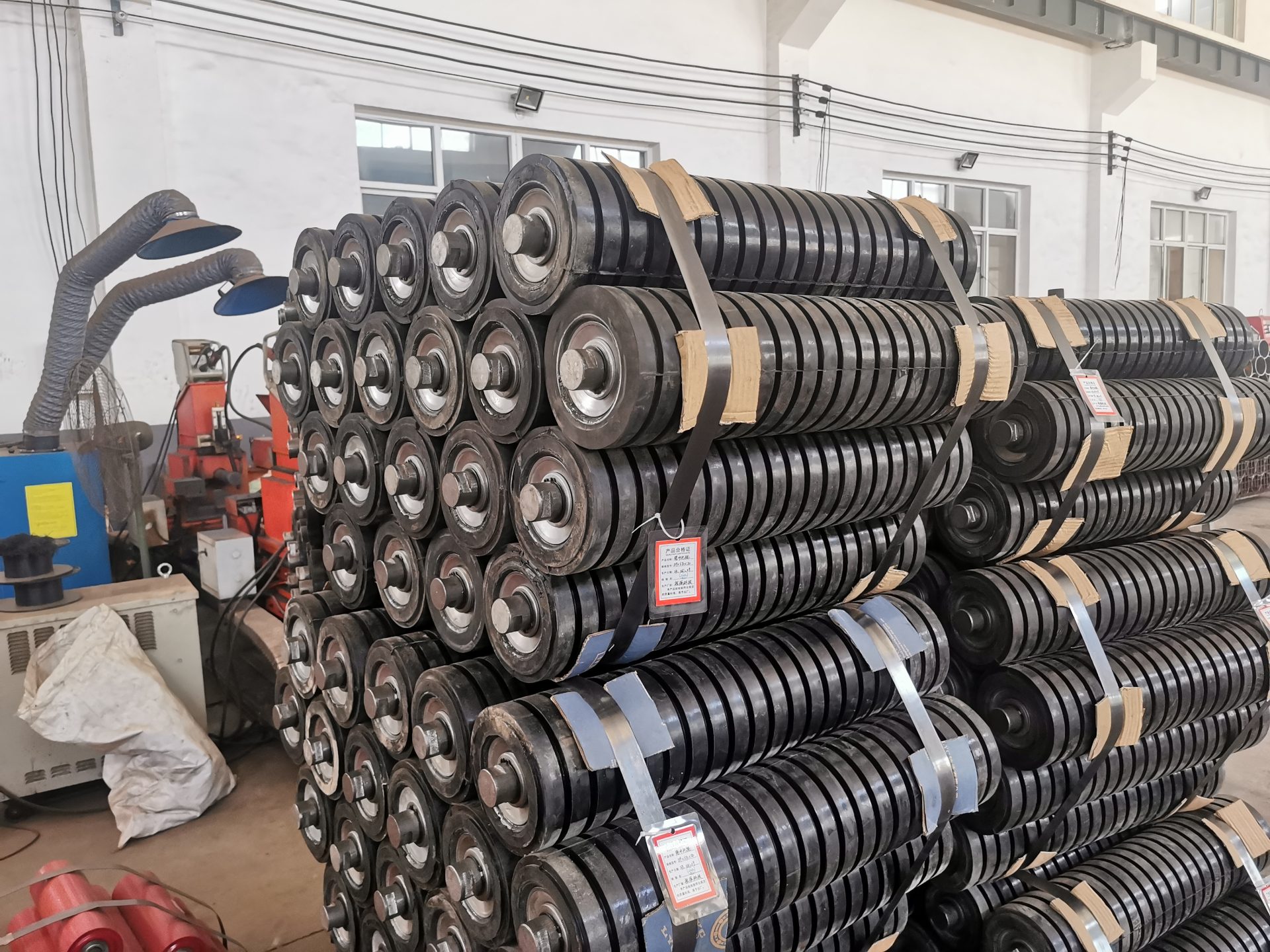
For a garland, the inter-roller links and suspension ends form part of the support arrangement. A roller approved for a rigid carrying station is not automatically approved for a linked suspended set. Confirm the actual connection and assembly construction rather than transferring a shell description between those positions.
Keeping these duties separate also improves quotation comparison. A proposal for an individual roller, a linked group and a complete support station represents three different supply objects. Identify which one each price includes before treating a cheaper line as an equivalent offer.
Keep the Approved Steel Roller Construction Attached to the Delivered Components
Once the load and assembly have been assessed, give the supplied components a reference that identifies the approved construction and location. Where several long rollers share a diameter but differ in shaft or bearing arrangement, a common diameter label is insufficient. The receiving team needs a way to distinguish the actual approved assemblies.
Agree transport protection for the working faces and projecting shaft ends. The proposed supports and restraints should suit the components being supplied, with the handling method based on their actual mass and geometry. Do not use a product photograph to infer package weight or a safe lifting arrangement.
At receiving, compare the assembly with the final approved drawing, including the face length, support relationship and end features. Record visible damage before fitting. If a roller arrives with an unapproved construction change, separate that issue from a routine receiving tolerance discussion and obtain the appropriate technical decision.
The existing steel roller and bearing explanation provides additional construction context. For the actual purchase, retain the load-position drawing and the complete approved assembly details together. A long steel roller becomes an appropriate replacement when its shell, bearings and shaft support the defined duty—not when its outside diameter merely resembles the old component.
Last Updated on October 2, 2026 by gramconveyor_admin


