
Mining Conveyor Rollers Supplier: Matching a Shutdown Replacement to the Existing Frame
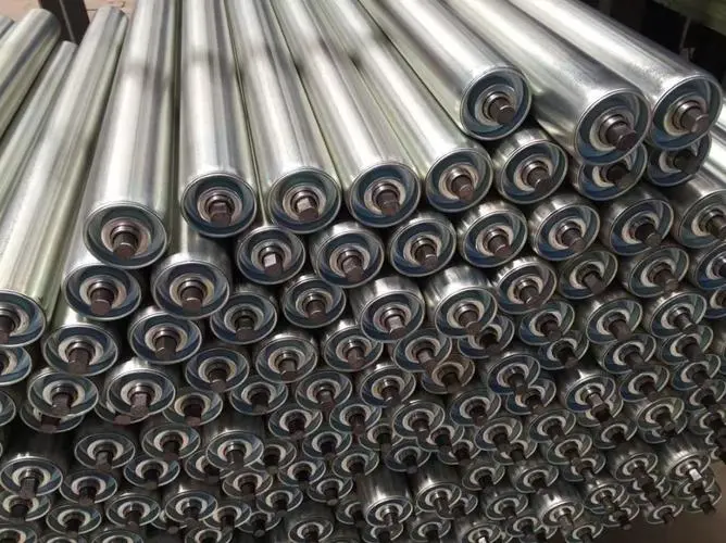
A shutdown date can be fixed while the replacement roller specification is still uncertain. For a mine maintenance planner, the useful mining conveyor rollers supplier is the one that can match the installed frame, the duty at each position and the operating environment—not merely offer a tube with the right outside diameter. Start with GRAM’s steel conveyor rollers for the carrying positions, then separate impact, suspended and tracking components before releasing the order.
Give the Mining Conveyor Rollers Supplier the Installed Frame Interface
The roller shell is visible, so it often becomes the first dimension recorded. The installation interface is less obvious but can stop the replacement from being fitted. A shaft may have flats, slots or another end arrangement that locates it in a particular bracket. The face length, overall shaft length and distance between supports describe different things. Put them on one marked drawing rather than sending several photographs with an unlabelled length.
For a contractor replacing an old idler bank, the complication may be inconsistent modifications along the conveyor. One frame has been repaired, another has a different retaining arrangement, and a third has been moved to accommodate a chute. Treat those positions as separate interfaces until measurement shows that they are interchangeable. Do not turn a mixed installation into a single stock item by averaging its dimensions.
Steel Roller Shafts Must Seat in the Existing Brackets
GRAM’s steel roller range is relevant to carrying heavy material, but a steel shell alone does not establish fit. Confirm where the shaft bears on the bracket, how it is retained and whether removal clearance remains available after the belt is supported. A change in shaft length can affect both installation and access. An apparently stronger roller can be awkward to replace if the revised shaft cannot be lifted out of the existing frame.
When the old component is badly worn, measure an unworn representative from the same position as well. A damaged shaft end, distorted bracket or worn retaining slot should not become the reference geometry for a new production batch. If the frame needs repair, decide whether the order will reproduce the original interface or match a deliberately revised frame. Those are different engineering instructions.
Mark the roller face relative to both shaft supports, not only its total length. An offset face can place the working surface differently under the belt even when the overall shaft length appears correct. On a troughing station, the centre and wing positions may also have different interfaces. Keep their drawings and quantities separate until the responsible engineer confirms interchangeability. This avoids opening a shipment of apparently identical steel rollers and discovering that only one position can use them.
For a replacement sample, request identification that follows the approved drawing revision and conveyor position. A photographed shaft end should carry an orientation label so the supplier can distinguish the drive-side view from the opposite end. Retain that labelled reference with the order. If a later clarification changes a flat, slot or retaining detail, update the drawing rather than relying on an email instruction that the receiving crew may never see.
The Rulmeca conveyor roller catalog separates roller diameter selection by speed from roller selection by load. That distinction is useful here: matching the visible diameter is a compatibility check, not a complete load assessment.
Which Mining Conveyor Rollers Belong in the Shutdown Order?
A mine conveyor contains different support duties. Carrying rollers support the loaded belt, loading-zone rollers experience incoming material impact, and suspended sets have their own connection and movement requirements. The replacement list should identify these positions explicitly. Buying one roller construction for every location can leave the transfer point under-protected while adding unnecessary cost elsewhere.
| Position being replaced | GRAM family to examine | Interface that needs agreement |
|---|---|---|
| Regular carrying position | Steel conveyor roller | Face length, shaft ends, bracket support and rated duty |
| Material landing zone | Conveyor impact roller | Working diameter over the rings, support arrangement and impact duty |
| Suspended carrying station | Carrying garland | Connections, suspension points and assembled geometry |
| Tracking correction station | Self-aligning idler | Frame movement, belt contact and installation position |
Impact Roller Rings Belong Where the Material Lands
GRAM’s conveyor impact rollers support the belt where incoming material creates an impact load. Their rubber-ring construction should be considered together with the material landing position. The working diameter over the rings, their arrangement and the support below the belt matter; the steel tube diameter underneath is not the whole installed dimension.
Consider a quarry transfer where coarse material falls onto a short bank of rollers. If the most damaged components sit immediately below the material stream, the replacement question is not simply whether to buy thicker carrying rollers. Review the loading arrangement, impact support and belt protection together. An impact roller can address a support duty; it cannot correct a badly positioned chute or remove oversize material from the feed.

Carrying Garland Connections Are Part of the Replacement
The carrying garland range is a different assembly from a set of independently mounted rigid rollers. Its linked arrangement provides a suspended carrying station. The connecting pieces and suspension interface therefore belong in the order, not in a later discussion after the rollers have been delivered.
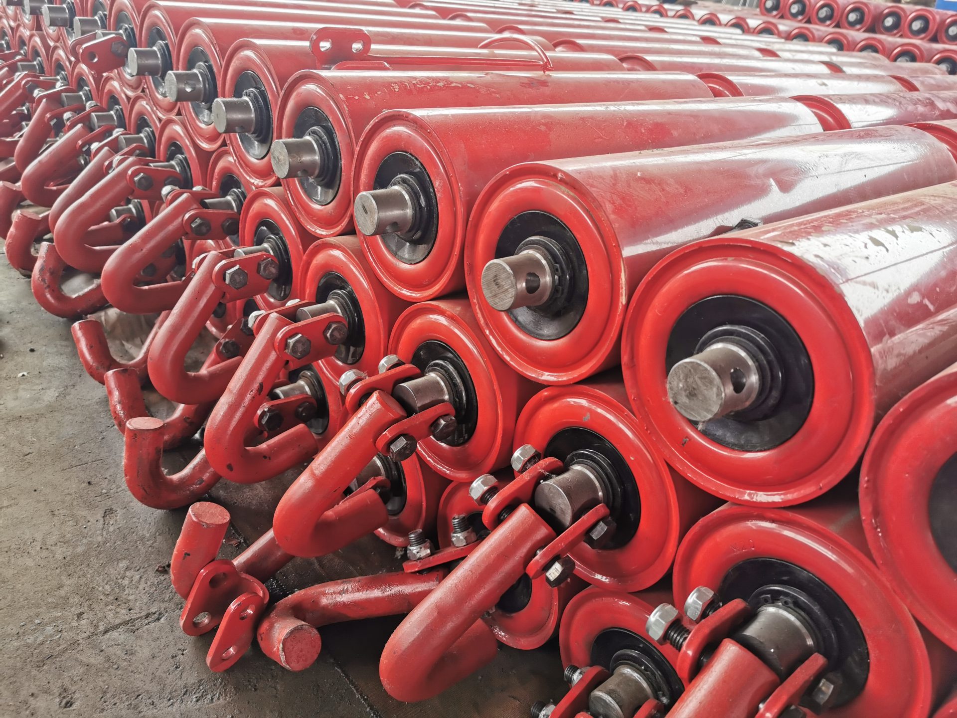
Photograph a complete installed garland from a safe position, mark the conveyor direction and record which connecting parts will be retained. If only the roller bodies are being replaced, establish that the retained connections are suitable. If a complete assembly is intended, list that clearly. A photograph of a garland laid on the ground does not, by itself, define its installed geometry or suspended operating envelope.
A Mine Roller Bearing Arrangement Must Match the Contamination Route
Dusty ore handling, wet fines and intermittent washdown create different conditions around roller ends. Record what reaches the bearing area: airborne dust, slurry splashing from below, material carried back on the return belt or cleaning water directed across the frame. The material name alone is not enough to describe those exposures.
GRAM’s polymer rollers provide a relevant construction to compare: a machined polymer tube or solid bar, sealed precision bearings, non-contact rubber seals and metal end caps. These are construction details, not a blanket guarantee for every wet or abrasive mine. The buyer still needs the proposed assembly’s allowable load, speed, temperature and chemical exposure confirmed for the intended position.
Polymer Tubes Need the Same Load and Bearing Review as Steel Tubes
A lighter roller body can be attractive where maintenance access is difficult. It does not remove the need to establish the duty on the bearing and shaft. Compare the proposed polymer construction with the installed steel assembly using the same position, belt speed and support geometry. Otherwise the decision becomes a comparison of material names rather than of complete rollers.
Ask for a section drawing that identifies the bearing, sealing arrangement and end cap. If the order changes the tube material but retains the shaft interface, show that relationship explicitly. If it changes both, assess both changes. The Metso heavy-duty roller brochure illustrates how sealing and runout are treated as distinct design considerations. Its proprietary construction belongs to Metso; it is not a specification or performance claim for a GRAM roller.
Do not write a promised service life into the comparison without an agreed basis. Actual life depends on the duty, contamination, alignment and handling as well as the component. A supplier’s construction drawing and the mine’s failure observations can support a better decision than an unsupported statement that one material always lasts longer.
Separate Mine Belt Tracking Problems from Worn Roller Replacement
A seized or damaged roller can affect belt travel, but replacing it does not prove that the frame, loading pattern and belt alignment are correct. Before adding tracking equipment to the same order, identify whether mistracking is local to a damaged support or persists along several stations. That distinction affects which GRAM products deserve consideration.
Self-aligning Idlers and Guide Rollers Perform Different Jobs
GRAM offers both self-aligning idlers and guide rollers. A self-aligning assembly provides a tracking-related support arrangement; a guide roller contacts and guides the belt at its designated location. Neither should be treated as a universal substitute for correcting skewed frames, uneven loading or damaged belt edges.
A maintenance planner may find that only one transfer area mistracks after a feed change. In that situation, examine the material landing pattern and surrounding supports before replacing every station with a tracking device. If a self-aligning assembly is selected, confirm its permitted movement and clearance. If a guide roller is selected, identify its contact surface and position without assuming that continuous force against an already damaged edge is acceptable.
The Sandvik conveyor components application brochure distinguishes component functions across a conveyor system. It supports a position-by-position review; its models and ratings must not be substituted for the proposed GRAM equipment.
Release the Roller Order in the Sequence the Shutdown Can Use
First agree the fit-critical drawing for each distinct position. Then agree which assembly is being supplied, which parts remain on the conveyor and which checks demonstrate conformity. For a steel carrying roller, that may mean the shaft-end geometry and shell dimensions. For a garland, it includes the assembled connections. For an impact roller, it includes the working ring arrangement.
Identify the dimensional checks on the approved drawing and agree the inspection record before shipment. Runout or starting resistance limits, where required, should be supplied by the responsible engineer or agreed technical specification; this guide does not assign universal acceptance values. Avoid requesting an impressive-sounding test that has no defined method or connection to the actual failure risk.
Packaging must preserve those fit-critical features. Ask how shaft ends will be protected, how ringed rollers will be supported and how linked garland sets will be identified. Agree separate package labels for carrying, impact and suspended positions. Record these protection measures and labels in the order instead of assuming that a particular packing arrangement is included.
For the shipment plan, distinguish production completion from dispatch, transport and receipt at the mine. A shutdown order needs an agreed receiving window and time to check the delivered interfaces. No general product description can confirm that window. If a sample or first assembly is needed for a trial fit, make that approval stage explicit before the full quantity is released.
Physical measurement and trial fitting must follow the site’s isolation procedures. The Occupational Safety and Health Administration’s hazardous-energy guidance explains the importance of controlling energy during maintenance. Apply the mine’s local requirements and approved work procedure; photographs or measurements never justify reaching into an operating conveyor.
For a wider view of the installed components, GRAM’s mining conveyor belt roller overview explains the roller families, while the coal-mining steel tube return roller article addresses a different belt position. Use that context to identify the assembly, then return to the measured frame drawing.
Before the shutdown order is approved, the maintenance planner should be able to place the replacement drawing beside the installed frame record and explain every difference. If the shaft ends, retained connections or roller position are still ambiguous, resolve them while the conveyor is available for a controlled inspection—not when the replacement pallets are opened beside a stopped production line.
Last Updated on October 2, 2026 by gramconveyor_admin


