
Tell a Belt Conveyor Carrying Rollers Supplier Which Position Each Roller Occupies
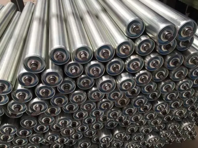
A pile of removed carrying rollers can look like a useful sample until nobody can say which unit came from the centre of a station and which came from an inclined wing. For a contractor replacing worn supports, the first task is preserving those positions. A belt conveyor carrying rollers supplier needs the retained station arrangement, the roller’s actual location and its mounting relationship before offering a replacement. Start with GRAM’s conveyor roller range, then separate the material and working-surface choices for each position.
The order should describe rollers for the conveyor that will receive them. It should not assume that every roller removed from the same belt is interchangeable. An ordinary carrying position, a loading position and a suspended linked group can require different supplied constructions even when the outside bodies appear similar.
Carrying roller positions must survive removal from the station
Identify the position before a removed roller becomes an anonymous workshop sample. The centre support and wing supports have different relationships to the belt and retained brackets. A photograph of the whole station, accompanied by a clear location reference, is more useful than several unlabelled close-ups of individual cylinders.
- Identify the conveyor and station in the plant’s existing equipment references.
- Mark the removed unit’s centre or wing location and the viewing direction used.
- Keep that location attached to the relevant dimensions and mounting details.
This key is not a new naming standard. Its purpose is to prevent the supplier and installer from assigning the same description to different physical positions. Use the plant’s established references where they are clear, adding a simple sketch where the existing record is incomplete.
The centre carrying roller belongs to the retained cross-section
The centre roller’s working length and shaft ends need to fit the actual supports that remain in service. Its position also contributes to the belt’s cross-sectional support. A replacement that fits between two brackets still needs to correspond to the intended carrying arrangement; bracket fit alone does not describe the whole station.
If the centre roller has been removed from a modified frame, record the modification instead of relying solely on an old general drawing. The supplier should receive the current accepted arrangement. Keep any disagreement between the drawing and measured retained equipment visible until it is resolved.
Wing roller descriptions need a clear side and viewing direction
An inclined wing roller can be misidentified when “left” and “right” are written from different viewpoints. Specify the orientation used in the sketch rather than expect the supplier to guess. Where the retained station uses identical wing units, that equivalence should come from its accepted construction, not from their similar appearance in a photograph.
A contractor should keep the ends of each sample identifiable as well. If an end feature or bracket relationship differs, rotating a sample for the photograph can conceal that difference. The separate discussion of roller locating dimensions helps define functional endpoints; the position record explains where that defined roller belongs.
A carrying rollers supplier should separate body material from station identity
Once the locations are clear, compare the actual body and end constructions offered for them. GRAM has steel and polymer roller routes, but a shared carrying role does not establish an identical assembly. An alternative material should remain a distinguishable proposal tied to the same retained position.
Steel carrying rollers retain a body, bearing and shaft relationship
GRAM steel conveyor rollers use a cylindrical steel body rotating around a central axle, with bearings toward the ends and projecting shaft interfaces. Those are relevant construction details for a retained carrying position. They do not supply a universal load rating or an automatic match to every frame.
Specify the working body and the mounting ends as separate parts of the replacement description. A similar tube length can conceal different overall shaft dimensions. Conversely, matching shaft ends does not prove that the working body gives the intended belt support. The accepted offer needs both relationships.

Polymer carrying rollers require an accepted complete alternative
The GRAM polymer roller description includes a machined polymer tube or solid bar, sealed precision bearings, non-contact rubber seals and metal end caps. These details help define what changes when the buyer considers a polymer body. They do not establish that every part of the assembled roller has the same environmental resistance as its body.
For a plant considering polymer wing rollers beside retained steel centre units, preserve the proposed mixed arrangement explicitly. Ask which positions the alternative covers and which remain unchanged. Do not infer a complete station approval from one material description, or assume that a lighter-looking body can replace a selected steel assembly without a position-specific review.
External descriptions of upper carrying and troughing arrangements illustrate why rollers and their support layout are considered together. That general engineering distinction is useful here; another manufacturer’s angles, frames and ratings are not specifications for the GRAM offer.
Loading-zone carrying positions need a separate working-surface decision
A carrying roller under incoming material is not automatically an ordinary carrying roller with a different location label. The loading duty can change the required working surface and support arrangement. GRAM’s rubber-ring impact rollers provide a distinct route for that discussion.
The rings belong to the belt-contacting working construction, while the underlying roller body and shaft ends still need to fit the accepted supports. Identify both. An outside ring diameter is not a substitute for the dimensions and relationships of the complete assembly.
A distributor combining an ordinary carrying order with loading-zone replacements should preserve those line items separately. Otherwise a request for “carrying rollers” can conceal a ringed construction that was expected at only a few stations. The supplier needs to know which duty the rings address, rather than add them to every position or omit them from the loading supports.
Where the plant changes the loading arrangement, the retained roller sample supplies mounting evidence but may not describe the new duty. Keep the revised material entry and support requirement alongside the sample identity. The responsible project team should accept the offered arrangement for that change; this article does not prescribe impact capacity or spacing.
Suspended carrying groups cannot be ordered as anonymous loose rollers
GRAM carrying garlands use connected rollers in a suspended group. The component’s location within that group and its connection relationship matter alongside its body dimensions. A loose roller from a garland should not be assigned to a rigid carrying station simply because it looks like a cylinder of the right size.
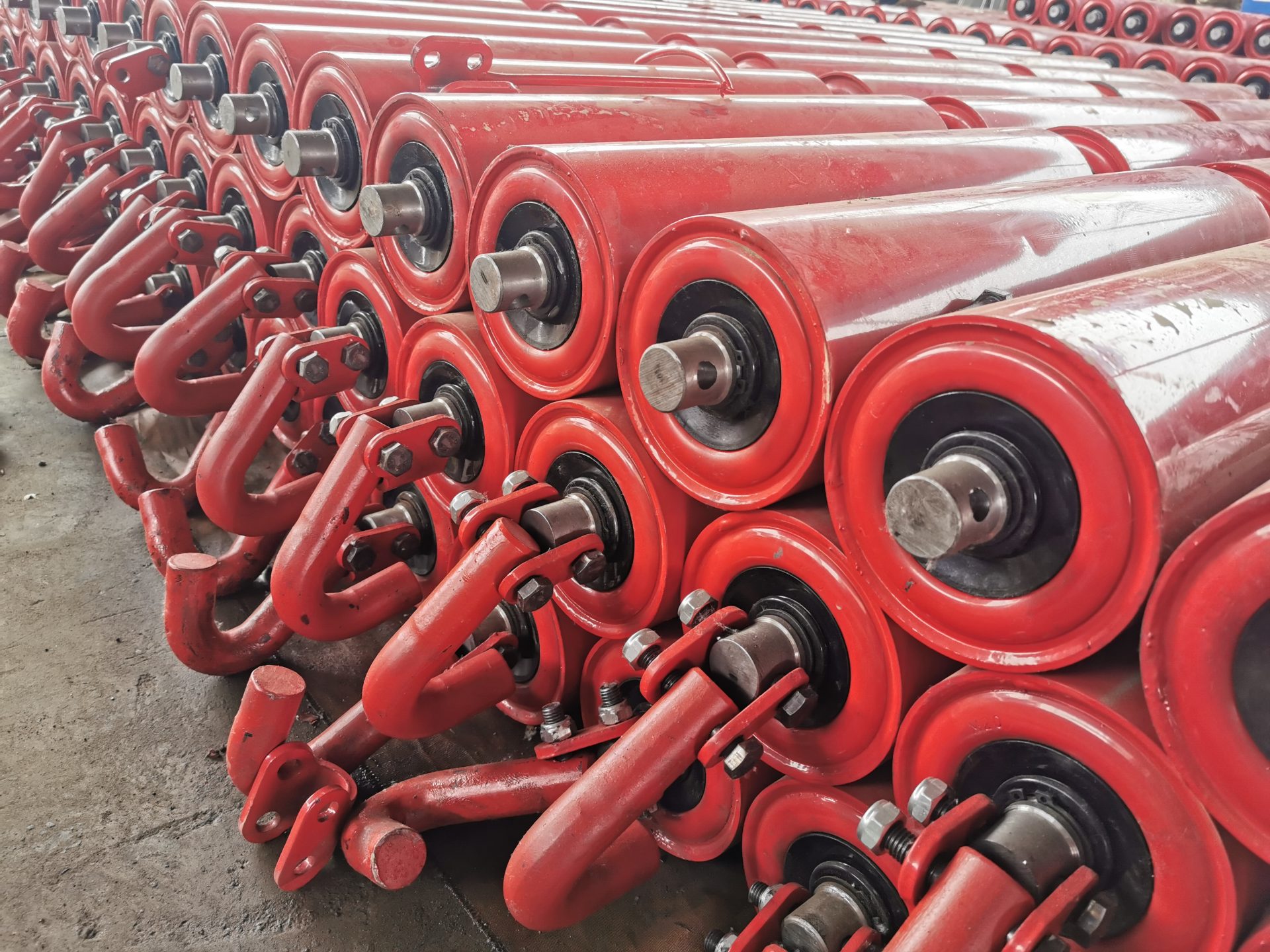
If the buyer wants only part of an existing garland replaced, define the retained group and the connection scope of the supplied parts. If the entire group is being purchased, identify it as an assembly. The same photograph should not be used to imply that unspecified suspension hardware is included in both offers.
The receiving team also needs to distinguish loose components from complete supplied groups. Keep their references visible on the actual delivery information. Packaging details and grouping should be agreed for that order; a product photograph does not establish the supplier’s standard packing practice.
Carry the position key through the replacement order
Consider a shutdown order containing centre rollers for one conveyor and wing rollers for another. The tubes may appear similar on the workshop rack, while the shaft projections or bracket seats differ. Separate the destinations in the order even when the supplier groups their manufacture or transport. The contractor should be able to check a delivered item against its intended retained station without dismantling a second sample to rediscover the distinction.
If a loading station has several ringed rollers among neighbouring plain supports, mark where the ringed construction begins and ends in the accepted arrangement. A close-up of one impact roller cannot establish that boundary. The location sketch gives the supplier a reason for the different working surfaces and gives the installer a clear destination for each accepted item. Keep this as a component assignment record rather than a claim that the described transition has already been engineered for a changed feed.
Use the same location references in the quotation, accepted construction and receiving information. Where the supplier consolidates equivalent units into a single item, preserve the list of positions that equivalence covers. A contractor can then distribute the accepted replacement without recreating its identity at the conveyor.
When a delivery contains several similar roller bodies, the package identification should help separate centre, wing, loading and garland items according to the accepted offer. Agree that requirement before dispatch rather than assume an undocumented labelling service. It is a practical way to protect the position information already used to select the assemblies.
Resolve a position mismatch before treating a delivered roller as interchangeable. The useful purchasing decision is not simply “steel or polymer”; it is the accepted construction for a named place on the retained conveyor. Keep that place attached to the roller all the way from removal to the replacement order.
Last Updated on October 3, 2026 by gramconveyor_admin


