
Check the Bar Removal Path Before Choosing a Conveyor Impact Bed Supplier for a Retrofit

The impact bed fits beneath the belt, but a worn support bar cannot be withdrawn without removing nearby structure. An aggregate transfer-point contractor should resolve that problem before choosing a conveyor impact bed supplier for a retrofit. GRAM’s loading-zone belt support range includes beds, saddles and idlers. For an impact-bed proposal, start with the retained frame, belt geometry and the actual component removal method. Installation clearance and future service clearance are two different approval questions.
A bed can be the intended support route while its proposed arrangement remains unsuitable for the available space. The retrofit review should explain how the unit will be mounted, how the belt will be supported during approved maintenance and how the wearing components can leave the installation. A drawing that shows only the assembled bed under the conveyor does not answer those questions.
Ask the Conveyor Impact Bed Supplier How a Worn Bar Leaves the Installation
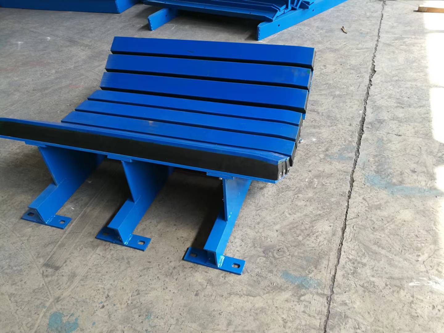
GRAM’s existing bed photographs show longitudinal supporting bars on fabricated frames, with central and inclined side regions. Those visible components make a useful starting point for an access discussion. They do not identify a universal withdrawal direction or a standard modular removal feature. Ask how the particular proposed unit is serviced.
The Bar Removal Direction Needs a Defined Clearance Envelope
A contractor may have enough room to bring a complete bed into an unfinished transfer point but much less room after skirts, guarding and adjacent equipment are installed. Identify the proposed withdrawal direction for the actual wearing component. Then compare the required movement with the completed installation, not with the space available during initial construction.
If a bar slides out, the reviewer needs its removal route and the parts that must first be released. If another method applies, document that method instead. Do not infer the service arrangement from the fact that the bars appear separate in a photograph. The offered construction, fixings and access requirements must agree.
Show obstructions along the removal path: retained steelwork, chute supports, cables, guarding and other equipment. Identify which are fixed and which can be removed through an approved maintenance procedure. A service path relying on dismantling unrelated structure should be visible before the installation is accepted as a maintainable retrofit.
The fixing access belongs to this review too. A bar may have a clear withdrawal path while its retaining feature remains unreachable behind a chute member. Ask which tools and approach directions the actual construction requires, then assess that access against the finished structure. If the drawing assumes access from below, show what occupies that space and how the approved maintenance arrangement reaches it.
This keeps the removal assessment specific to the offered bed: movement clearance and fixing access must both exist for its wearing component.
For a mine maintenance engineer, the important distinction is not whether a technician could somehow extract the component. It is whether the proposed method is workable under the site’s approved equipment-control and access procedures. A supplier drawing cannot replace the site’s safe method for isolating the conveyor and supporting the belt.
Side-region Components May Need Different Access from Central Bars
The inclined side regions shown in GRAM’s bed photographs do not occupy the same geometry as the central region. A proposed removal method should identify how each relevant component is reached. Access to a central bar alone is not evidence that a side-region component can be exchanged within the retained structure.
At a narrow transfer station, a skirt or frame member may obstruct a fixing on one side while the other side is open. Record both sides rather than presenting the more accessible side as representative of the whole bed. If the proposal requires a removable part to create access, include that part and its approved scope in the retrofit design.

The Conveyor Impact Bed Supplier Needs the Retained Mounting Structure
Once the service path is understood, establish how the complete unit mounts to the conveyor. GRAM’s photographs show fabricated support structure and mounting feet. Their appearance does not establish hole spacing, fixing capacity or compatibility with the existing steelwork. Those particulars belong in the offered unit’s drawing and the project’s structural review.
Mounting Feet Must Match an Approved Load Path into the Frame
A buyer retaining the lower structure should show the mounting locations and the condition of the available supports. Compare the proposed feet, fixing arrangement and installed height with that structure. Do not treat an apparently convenient hole position as approval of the load transferred through it.
If the original support was a roller station, the bed’s attachment and load distribution may differ. The engineer should assess the complete change, including any new cross-members or other approved supporting work. A component that fits between the conveyor sides can still require an installation scope beyond replacing the old rollers.
Keep existing damage visible in the review. A worn, deformed or repaired support should not become an unquestioned reference just because it is staying on the conveyor. Establish which retained elements are serviceable and which must change before the bed proposal is approved.
Bed Height Should Be Reviewed Against the Intended Belt Path
The installed height affects how the belt meets the support and adjacent stations. Identify the intended belt path, retained equipment and the proposed support position on the same drawing. A bed that can be bolted down is not necessarily positioned correctly for the working belt.
A contractor replacing several support elements should distinguish a true retrofit drawing from a catalogue outline. The retrofit drawing needs to show the bed’s relationship to the conveyor, including the transition to retained support upstream and downstream. If that relationship depends on an adjustment, identify how the offered assembly achieves it.
Do not invent a universal support gap from product photographs. The appropriate installed relationship belongs to the selected construction and the engineering agreement. The purchase should carry those agreed requirements so the installation team is not asked to create them after the parts arrive.
Confirm the Belt and Adjacent Supports Before Freezing the Retrofit
The bed is selected for the belt and loading duty, not as an isolated frame. Record the belt width, construction and intended trough relationship alongside the proposed assembly. GRAM’s mining conveyor belt range offers relevant belt routes, but a range name does not establish compatibility with an unnamed support unit.
Retained Carrying Rollers Still Define the Approaches to the Bed
GRAM’s steel carrying rollers are a separate rotating support family. Where those rollers remain beside a new bed, their geometry and condition belong in the retrofit review. The transition should be assessed as a relationship between the bed, belt and adjacent supports.
If the retained roller station has moved or deteriorated, a bed drawing referenced to its current position can preserve an undesirable belt path. Establish the intended condition after any support repairs. Then confirm that the proposed bed and remaining rollers belong to that approved geometry.
For a transfer-point maintenance buyer, also identify whether the belt construction is staying. If a belt change and a support change are planned together, the bed should be assessed against the proposed belt, not only against the removed one. Keep the two supply scopes connected in the engineering record.
Rubber-ring Impact Rollers Remain a Distinct Support Alternative
GRAM’s impact roller assemblies use a rotating, ringed support route. A bed and an impact roller station should not be treated as equivalent simply because both are considered for loading duty. The chosen route must fit the approved material-support and installation requirements.
This distinction also affects maintenance scope. A roller replacement and a bar replacement involve different components and access arrangements. If a project changes from one route to the other, explain the future wearing-component supply and service method as part of the change rather than leaving it to the maintenance team to discover.
Metso’s conveyor solutions handbook treats impact support as a defined conveyor component selection. Its assemblies and ratings belong to Metso. The general engineering point is to approve support for the actual loading position, while the retrofit additionally needs the particular unit’s mounting and service arrangement.
Define Which Impact-bed Components the Retrofit Order Supplies
GRAM’s conveyor accessories range provides a broader route for the associated component discussion. For the actual bed, the order should identify the assembly, wearing parts, fixings and any agreed supporting components. A picture of a complete unit does not establish what a particular quotation includes.
- The offered bed assembly: the exact frame and support arrangement identified on the approved drawing.
- The wearing components: the actual bars or other parts, their identifiers and their confirmed replacement method.
- The mounting boundary: supplied fixing components and the retained or separately modified conveyor supports.
- The service boundary: removable parts or access provisions required for the agreed component replacement.
If a quotation covers only replacement bars, confirm that they suit the retained assembly. Similar length and appearance do not establish matching fixing geometry or contact construction. Obtain confirmation of the actual compatibility rather than using a material colour or a generic “impact bar” description as the acceptance basis.
Conversely, a complete new frame should not inherit an old bar approval without review. A change to the supporting arrangement can change how the components are fixed and presented to the belt. The approval record should identify the new complete arrangement and the specific wearing parts that belong to it.
Plan Delivery Around the Bed’s Actual Assembled and Service Dimensions
The assembled unit’s handling envelope and the wearing component’s removal envelope are different. Keep both available for the contractor. The first helps establish how the unit reaches the mounting position; the second helps establish whether the finished installation can be maintained.
Ask how the proposed assembly will be supplied and protected in transit. The actual unit mass, lifting information and package dimensions should support the unloading and placement plan. The existing photographs show bed structures on the floor, not approved lifting points or a prescribed transport arrangement.
If bars or mounting parts travel separately, identify them by the assembly reference and intended position. Keep those identifiers with the components during unpacking so the installer can match them to the drawing. A collection of similar-looking pieces is not a complete installation instruction.
At receipt, compare mounting geometry and supplied components with the final approved revision. Record visible damage to the frame, contact surfaces or fixing features before placement. Resolve an unapproved change while the assembly is accessible, rather than after it has been enclosed by skirts and guarding.
Accept an Impact-bed Retrofit That Can Be Serviced in Its Finished Position
The existing loading-zone impact bed explanation provides broader context for support selection. For the retrofit, the decisive record is more specific: the offered assembly, retained mounting structure, belt relationship and confirmed wearing-component removal path.
Before approving the installation, compare that removal path with the completed conveyor arrangement. Identify any agreed removable obstruction and keep its scope in the maintenance documents. If access exists only before the transfer point is completed, the design has answered the installation question but not the service question.
Release the bed order when the contractor can explain how it reaches its mounting position and the maintenance team can explain how its wearing parts leave that same position later. That is the practical difference between a component that fits under the belt and a retrofit the site can continue to use.
Last Updated on October 2, 2026 by gramconveyor_admin


