
A Conveyor Impact Rollers Supplier Should Start with the Material Landing Zone

The damaged belt is beneath the chute, but the replacement request lists only roller diameter. A quarry buyer or mine engineer working with a conveyor impact rollers supplier should first establish where the material actually lands and how the belt is supported through that area. GRAM’s conveyor impact rollers are a relevant starting point for a rotating, rubber-ring support. Its impact load-zone belt support offers a separate route when an impact bed, saddle or different support arrangement needs to be considered.
The purchase is not settled by the presence of rubber on a roller. The support must suit the material landing footprint, the belt geometry and the forces transferred into the conveyor structure. Otherwise a stronger replacement may be fitted beneath the same poorly supported area and leave the original cause of damage unresolved.
Give the Conveyor Impact Rollers Supplier the Actual Landing Footprint
The material stream occupies an area, not a single point on a drawing. Describe its position along the conveyor and across the belt, together with the feed trajectory, largest relevant lumps and operating variations. Those details allow the engineer to assess whether the existing impact station arrangement supports the belt where the load is applied.
A quarry transfer may show repeated cover cuts between adjacent roller stations while the rollers themselves remain serviceable. Replacing only the rings can leave the same unsupported span beneath the incoming material. The investigation should compare the damage location with the station positions, not assume that every cut is evidence of insufficient ring hardness.
Large Lumps and Fine Material Load the Impact Bank Differently
A stream of fine material and occasional large lumps should not be reduced to one average feed description. An irregular lump can impose a localized loading event, while fine material may accumulate around the support and sealing area. Give the engineer the relevant material characteristics so both the structural and contamination questions can be assessed.
Material drop and direction matter as well as weight. Rulmeca’s impact roller technical material explains why impact support is assessed for the falling load and the base roller. Its models and dimensions are not GRAM specifications; the principle is to evaluate the assembly against the loading event rather than the static carried load alone.
At a mine transfer modified for a different feed route, the original impact bank may no longer sit under the new material trajectory. Mark the revised landing area before assuming that the old station quantities remain appropriate. If the load has moved, a like-for-like roller order can reproduce a support arrangement that no longer matches the chute.
Include the conditions under which the landing footprint was observed. A partly loaded feeder may produce a different stream from the intended production duty, and a brief observation can miss intermittent oversize material. The engineer needs the relevant operating range and the method used to describe it. That does not require inventing an impact-force value; it requires preserving the operating context for the support assessment.
Rubber-ring Impact Roller Geometry Determines the Supported Belt Line
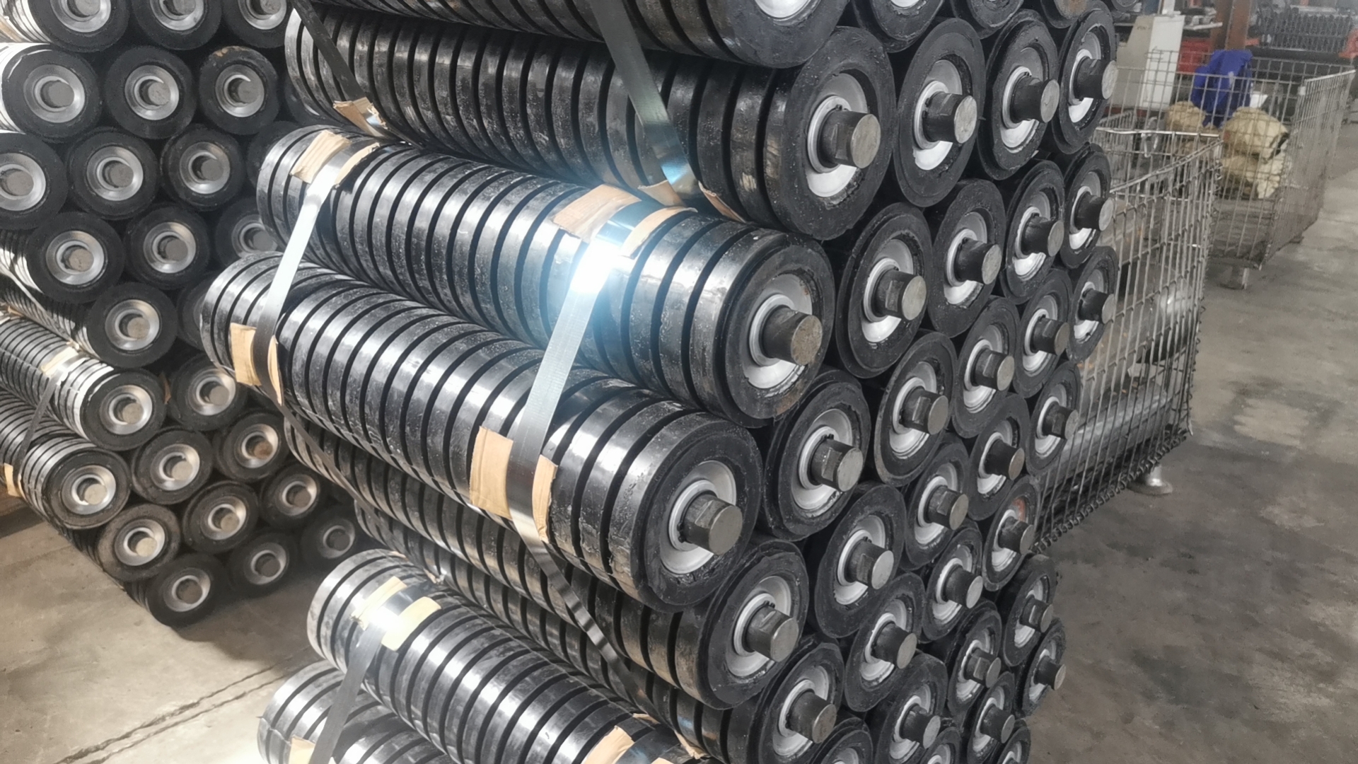
The rubber rings form the working surface of the impact roller. GRAM’s product images show the ringed body, roller ends and projecting shafts. The complete outside diameter over the rings matters to the belt line; the underlying tube diameter is only part of the construction.
The Ringed Working Diameter Must Match the Intended Impact Station
Confirm the proposed working diameter, ring arrangement and roller face length for the intended position. A change in the ringed diameter can alter the belt support height even if the base roller and shaft appear similar. The engineer should review that geometry with the surrounding carrying run before the new component is treated as a direct replacement.
Worn rings are a poor dimensional reference for a new assembly. If the old working surface has lost material unevenly, its measured outside profile may describe wear rather than the intended belt line. Use the original construction information where available, or establish the replacement geometry through an approved assessment.
Centre and Wing Impact Rollers Share a Troughing Decision
Where a station supports a troughed belt, the centre and wing positions work together. Their heights, angles and interfaces should preserve the intended belt shape through the loading zone. Do not approve each roller in isolation and assume that the assembled station will reproduce the required support profile.
A replacement wing roller with the correct nominal length can still change the supported shape if its working diameter or mounting arrangement differs. Keep the station-level drawing associated with the individual components. The order should identify which positions are being replaced and which retained frame parts establish the assembly geometry.
When an Impact Bed Addresses a Different Loading-zone Problem
GRAM’s loading-zone support range includes impact beds, saddles and idlers. A rotating roller bank and an impact-bed arrangement provide different support geometries. The choice should follow the observed loading problem and the conveyor design, not a claim that either option is always superior.
| Observed loading problem | Question for rotating impact rollers | Question for impact-bed support |
|---|---|---|
| Damage appears between support stations | Does the station arrangement support the actual landing footprint? | Would the proposed bed provide the required support through that area? |
| The belt moves beneath the chute sealing area | Is deflection compatible with the intended sealing arrangement? | How will the proposed support maintain the belt path and clearance? |
| Material accumulates around support components | Can the rollers rotate freely and remain accessible? | How will deposits, access and sliding-contact conditions be managed? |
Continuous Belt Support Introduces Its Own Operating Questions
A bed supporting the loading region needs an appropriate structure, contact arrangement and installation clearance. The buyer should obtain the proposed geometry and the design basis for the loading conditions. A more continuous support surface does not remove the need to assess the conveyor structure or the belt’s movement through the transfer.
The Metso conveyor solutions handbook illustrates that impact-cradle selection depends on an application-specific loading assessment. Its calculation assumptions and classes belong to Metso. A GRAM bed proposal needs its own agreed design information; the handbook should not be used to assign a borrowed capacity to an unspecified assembly.
If an existing conveyor has limited access beneath the chute, confirm how either support arrangement can be installed and maintained. An impact bed that addresses support continuity may still require a different access envelope from removable rollers. The engineering comparison should include the physical installation, not just the purchase price of the visible working elements.
The retained structure needs a defined assessment when the support route changes. A bed may connect differently from an existing roller station and transfer its loads through different mounting points. Confirm the proposed attachment and the structure that will carry it before accepting a retrofit. A component that fits beneath the belt is not thereby confirmed as suitable for the existing frame.
Carrying Rollers Should Not Be Ordered as Unspecified Impact Replacements
GRAM’s steel carrying rollers provide a different family to examine for the ordinary carrying run. A robust metal shell does not automatically establish suitability beneath the material drop. If the component is intended for impact duty, the proposed construction and rating must address that duty explicitly.
The transition out of the impact bank also matters. The belt should move from the loading support into the carrying arrangement without an unintended step or abrupt change in geometry. Review the adjacent stations when the impact roller working diameter or support arrangement changes. The loading-zone order should not create a new problem immediately beyond its boundary.
Check the belt line on both sides of the revised support, including the approach beneath the chute. If an adjacent station is retained, its original working geometry remains part of the comparison. A new ring diameter should not be approved as a single-component improvement without showing how those neighboring supports relate to it.
Mining Belt Construction Cannot Replace a Loading Support Assessment
GRAM’s mining conveyor belt range is relevant when the belt itself needs replacement. Belt reinforcement and covers still have their own requirements. Buying a belt described as heavy duty does not prove that a poorly supported material landing area is acceptable.
For a transfer with both cover damage and damaged impact supports, coordinate the two decisions. Identify what the belt construction must withstand and what the support must do beneath it. If one component is changed without reviewing the other, the buyer can spend on a stronger belt while retaining the same concentrated loading geometry.
Conversely, changing the impact support is not proof that an already damaged belt can remain in service. The responsible engineer should assess the belt’s condition and the repair or replacement requirement. The support supplier’s role and the belt acceptance decision need clear boundaries so neither is inferred from the other.
Off-centre Feeding and Mistracking Need a Separate Correction
An impact roller supports the incoming load; it does not automatically centralize an uneven material stream. If feeding is persistently off centre, review the chute and loading arrangement. Metso’s belt-life maintenance discussion identifies off-centre feeding and alignment as issues that affect belt travel.
GRAM offers self-aligning idlers as a separate tracking-related family. They should be considered against an identified tracking requirement, not added automatically to every impact order. A support device cannot be expected to remove the underlying cause of a badly positioned material stream.
Distinguish local deflection beneath the incoming load from persistent mistracking beyond the loading zone. The observations may occur together, but they lead to different questions. The impact bank needs to support the belt; the feeding and alignment assessment needs to establish why the belt is moving sideways.
Release Impact Roller Dimensions with the Loading-zone Arrangement
Before dispatch, connect the approved individual roller drawing to its station and conveyor position. The receiving team should be able to identify the working ring diameter, face length, shaft arrangement and assigned location. If more than one impact station construction is supplied, keep the references distinct through transport and receipt.
Ask for protection that suits the ringed surfaces and exposed shaft ends. Rings should arrive in the condition required by the agreed assembly, and the package labels should preserve the position references. A bundled product photograph illustrates possible handling, but the actual protection and delivery scope must be agreed for the ordered rollers.

For the product-family background, GRAM’s rubber-ring impact roller explanation provides additional context. Use it to identify the construction, then return to the actual landing-zone geometry and approved support arrangement.
Site measurement, removal and installation must follow the mine or plant’s approved isolation procedures. The OSHA hazardous-energy guidance explains the maintenance principle. A material trajectory should be observed from an approved safe location; it is never a reason to reach beneath a moving belt.
When the supplier’s proposal shows exactly how the belt will be supported under the material stream, the impact purchase has a clear basis. If damage still falls between the proposed support positions or the revised chute sends material beyond them, revisit the arrangement before ordering stronger rings. The useful replacement supports the real transfer, rather than repeating the dimensions of a loading zone that has already changed.
Last Updated on October 2, 2026 by gramconveyor_admin


