
How a Tapered Conveyor Rollers Manufacturer Should Read Your Conveyor Curve
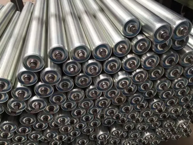
A curved conveyor drawing tells a roller supplier more than a photograph of a cone. An engineering buyer working with a tapered conveyor rollers manufacturer should identify the inner and outer load paths, mounting references and drive arrangement before requesting replacement rollers. GRAM lists tapered rollers in its specialized steel roller range for curved conveying. Start with that range and supply the actual curve geometry; do not assume a taper can be selected from the straight conveyor’s roller diameter alone.
The intended use is typically unit-load handling around a curve, where cartons, containers or components need coordinated support across the width. The first approval question is whether the offered roller geometry belongs to that curve and its mounting frame. Material, bearings and surface options follow that geometric decision.
A tapered conveyor rollers manufacturer needs the inner and outer paths
The outside of a curve follows a longer path than the inside. A tapered roller provides a changing running diameter across its working length, and its orientation matters. State which end is toward the inside of the conveyor and which is toward the outside. The drawing should make that relationship visible without depending on a verbal instruction from the installer.
The large end and small end need separate diameter references
Record the required running diameters at the relevant positions, rather than describing the assembly with one nominal diameter. If a sample has a sleeve or coated surface, identify whether the measurement refers to that finished surface or the underlying body. A supplier should not have to guess which part of the tapered assembly establishes the load contact.
GRAM describes tapered, grooved and sprocket rollers as different specialized steel variants. Those terms can identify geometry and drive features in the same assembly, but the actual combination must be confirmed. Do not infer that every tapered roller is offered with every drive arrangement merely because both appear in the overall range.
The conveyor curve radius belongs with the roller drawing
A curve radius helps explain the relationship between the roller geometry and the conveyor layout. Use the equipment designer’s reference for the radius and state whether it concerns the inner rail, centerline or another defined feature. Different reference locations can produce different numbers for the same physical conveyor.
An integrator joining a curved carton section to a straight conveyor should include the transition locations as well. The curve may be correctly drawn while the final roller creates an unsuitable step or gap at the adjoining section. Give the manufacturer the local mounting and contact geometry at these transitions so that the roller proposal can be evaluated as part of the complete load path.
| Curve input | Reference to establish | Why the buyer needs it |
|---|---|---|
| Working diameters | Large and small running surfaces | Identifies the taper and its orientation |
| Working length | Load-contact region | Separates support width from shaft projection |
| Curve geometry | Named radius or layout datum | Relates the roller to the correct conveyor path |
| Mounting span | Actual frame retaining surfaces | Confirms installation compatibility |
| Drive position | Groove or sprocket plane, if present | Keeps the transmission aligned |
Tapered conveyor roller replacement requires an orientation check
A loose sample can lose the information that was obvious while it was installed. Mark its inner and outer ends before removal, or obtain the orientation from the equipment drawing. Include photographs showing the shaft ends and any drive feature. That evidence prevents an otherwise accurate dimensional copy from being assigned to the wrong orientation.
A replacement buyer who receives only a tapered sample should identify what the sample can prove. It can show construction and measured dimensions in its present condition. It cannot, by itself, establish the original curve reference, load arrangement or approved new dimensions if the surface has worn. Compare it with the installation before finalizing the order.
Shaft-end dimensions must still fit the curved frame
The GRAM conveyor roller range discusses shaft-end choices including round, hex and spring-loaded arrangements. Select the end form that belongs to the existing curved frame. The taper does not remove the need to check shaft engagement, mounting span and clearance at both ends.
Frame access can differ on the inside and outside of the curve. If a projecting end, bracket or drive component is close to the frame, show that clearance on the installation drawing. A replacement may match the overall width yet interfere at one end because a different end assembly or component position was supplied.
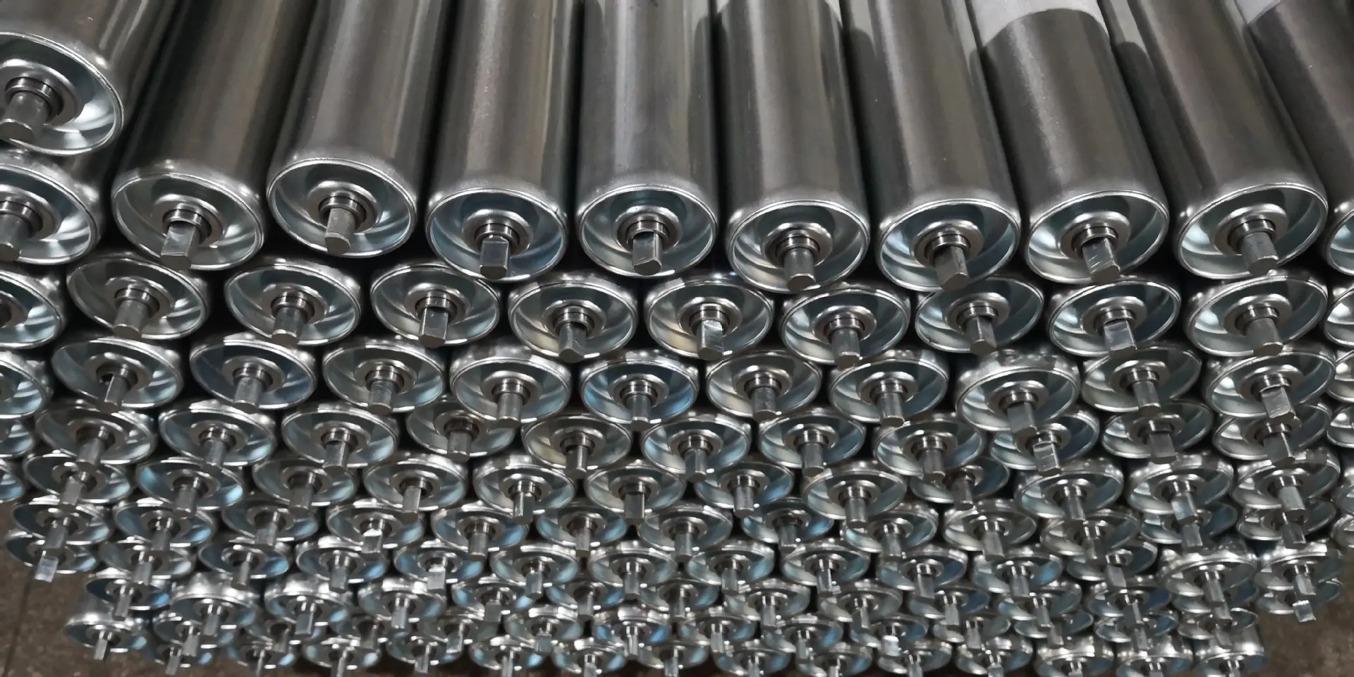
Choose the tapered roller drive route before approving the surface
GRAM’s roller conveyor range distinguishes gravity and powered conveying. A tapered roller may be considered within different movement arrangements, but the offered product must match the particular system. Identify whether the curve is free-running or driven and who owns the conveyor design approval.
Grooved tapered rollers must meet the existing drive plane
If a drive belt engages a groove, the groove position must match the existing transmission. Measure it from an agreed end reference and include the finished running surface in the drawing. A matching taper cannot compensate for a groove that places the drive belt outside its intended plane.
The groove itself also needs a defined interface with the existing belt arrangement. Ask for the offered groove geometry and the approved matching requirements. Do not assign a belt section, groove count or diameter from another manufacturer’s example to the GRAM product without confirmation.
Sprocket tapered rollers require chain-side clearance
A sprocket-driven arrangement needs the chain interface, sprocket position and clearance to guards or side frames. The chain-side envelope may be more restrictive on a curve than on an adjacent straight section. Include the retained transmission and guarding when discussing the proposed roller, especially if the old assembly has been replaced by a different component design.
Rolcon’s tapered roller information illustrates the connection between curved conveying and roller options. Its listed dimensions and drive configurations are model-specific external examples. They explain why geometry matters, but they do not establish GRAM’s available dimensions or product combinations.
Keep the curved load supported without turning guide rollers into carrying rollers
The roller working length and arrangement need to support the actual load base. Provide the smallest and most difficult-to-handle items, not only the largest carton in the system. A flexible base or an uneven load may interact with the curve differently from a rigid container. Have the conveyor designer assess support and movement using the real product condition.
GRAM guide rollers can be relevant to local guiding requirements. Their built-in bearings and guiding role should remain separate from the tapered rollers supporting the load. A guide should not be used to conceal an unresolved support or transition problem in the curve.

Evaluate tapered roller fit and carton behavior before delivery
Carton behavior at the curve entrance should be checked separately from roller fit
A roller can fit the curved frame while the load still enters the curve badly. Provide the approach direction, adjoining contact height and the actual load base to the conveyor designer. A skewed carton entering from the straight section should not automatically be treated as a defect in the taper. The transition and surrounding guides may need their own assessment.
For a mixed-product line, include items whose bases are short, flexible or uneven. Their support through the entrance can differ from that of a long rigid container. The curve layout should be evaluated with the relevant load conditions before the buyer approves a roller configuration for the whole range. No universal taper or spacing can be chosen from the product name alone.
Where the curved section is powered, the drive arrangement and running surface need to be considered together. A change in the finished tapered diameter or surface construction can affect how the roller contacts the load at different points along its length. Have the system designer assess the proposed geometry rather than combining a taper copied from one sample with a transmission copied from another.
A project delivery can contain mirror-image or differently driven curve assemblies. Ask that orientation remain identifiable after the packaging is opened. Marking only the roller’s nominal length makes those differences easy to overlook. The purchasing record should identify which installation position each approved assembly serves, so the crew does not have to infer orientation from the loose components.
Mark delivered rollers by orientation and conveyor position where several geometries occur in the same project. Check the large and small end dimensions, shaft interfaces and drive feature against the approved drawing. Inspect the working surface and rotation before installation. Any agreed runout or dimensional tolerance needs to be stated rather than judged from a generic product photograph.
Agree transport support that keeps tapered working surfaces and projecting ends from striking neighboring assemblies. Where the rollers have different orientations or drive-side arrangements, keep the identification attached during storage. The crew should be able to distinguish the required unit at the curve without sorting an unmarked collection of visually similar rollers.
The custom roller drawing discussion helps assign responsibility when the sample, frame and new conveyor layout do not agree. For this order, approve the curve rather than the cone: the tapered roller should belong to the identified path, retain the correct mounting interface and match the actual means of driving the load.
Last Updated on October 3, 2026 by gramconveyor_admin


