
Choose a Spring Loaded Conveyor Rollers Supplier for the Frame You Actually Have
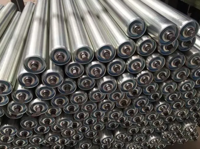
A roller that can be compressed into a frame is not necessarily retained correctly once installed. A maintenance team choosing a spring loaded conveyor rollers supplier should first identify the shaft engagement and frame openings that hold the roller in its working position. GRAM’s steel roller listings include a spring-loaded roller with a 1.5-inch diameter, alongside a 10-inch-long steel roller listing. Those descriptions provide a starting point; the replacement still needs a drawing matched to the actual conveyor.
This is principally a unit-load roller replacement question, such as a carton, crate or component transfer. It should not be confused with selecting an entire bulk-material idler station. Before asking for a price, record the roller body length, frame mounting span, shaft-end form and space available to retract the shaft during installation.
A spring loaded conveyor rollers supplier needs the retention geometry
The spring feature helps the shaft move during installation or removal. The conveyor frame must then capture the shaft ends as intended by the assembly design. State how that capture works on the existing equipment: frame holes, slots or another approved arrangement. A general instruction to supply a spring roller leaves the important retaining interface undefined.
Compressed shaft length and installed shaft engagement are different
The length needed to place a roller between the frames is not the same as the shaft projection needed after it has seated. Record both conditions on the drawing or obtain them from the equipment documentation. Do not infer the installed engagement from how far a worn shaft can be pushed into an old sample.
A workshop changing a roller between fixed side frames may have little room for its hands or tools. That makes the installation movement important, but it does not justify shortening the retained engagement. The offered design should fit the available installation space while preserving the approved mounting arrangement. Resolve any conflict before the shutdown rather than adapting the frame without review.
Round and hex shaft ends should remain explicit in the order
GRAM’s main roller range describes round, hex and spring-loaded shaft arrangements. These descriptions concern different interface features and can appear together in a complete specification. A spring-loaded construction does not establish whether the retaining end is round or hexagonal.
If the existing frame is designed for a particular end form, retain that information in the enquiry. A different form can change how the shaft sits or is prevented from rotating. The body may look identical while the mounting interface is wrong. Check an unworn frame opening and the approved drawing rather than relying on visual similarity between replacement tubes.
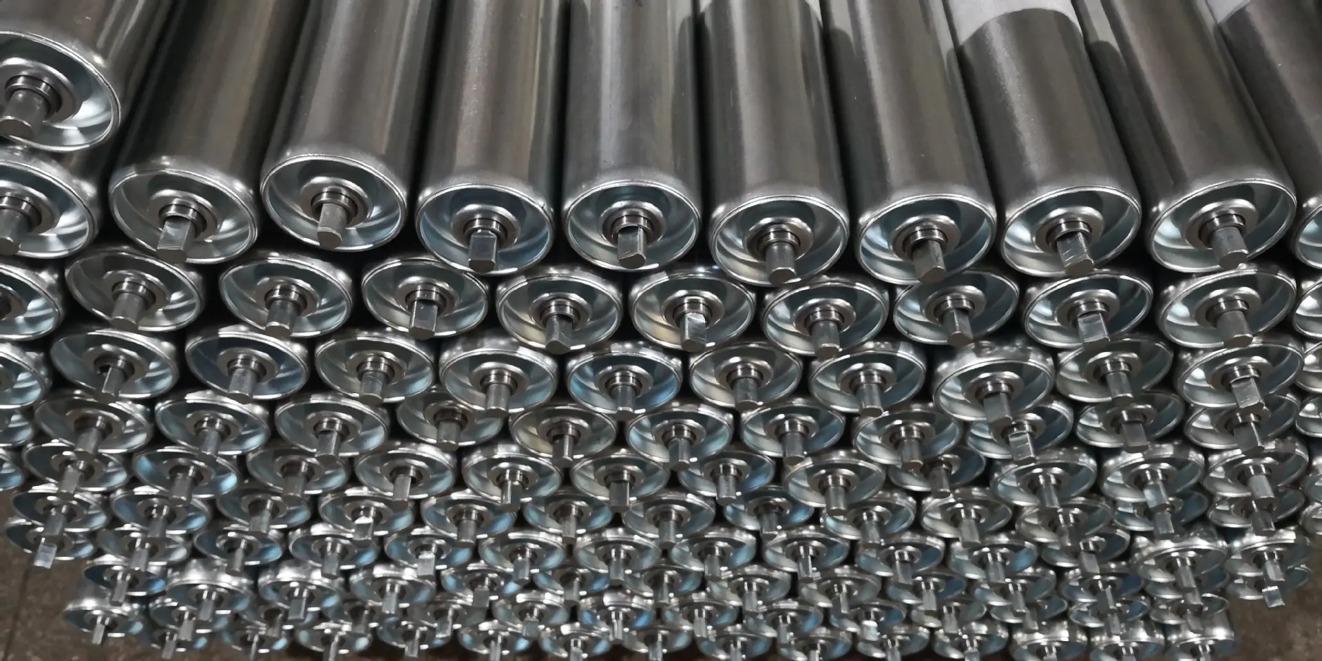
Spring loaded conveyor roller replacement starts with a usable sample
A returned sample is valuable only when its condition is understood. Bent shaft ends, worn seating surfaces or a damaged spring mechanism can distort the dimensions needed for the new assembly. Identify those faults and compare the sample with a working roller in the same conveyor section where possible.
A distributor receiving a loose roller from a customer should ask which conveyor position it came from and what the customer expects to retain. Was the existing roller free-running, driven or used next to a guide? Did it fail mechanically, or was it removed because the handled load changed? These answers determine which information the sample can establish and which information the supplier still needs.
Body length must not replace the frame mounting span
The body occupies the contact area beneath the load; the frame retains the shaft ends outside or beyond that area. A 10-inch body description, for example, does not specify every mounting dimension. GRAM’s steel listing should therefore be read as a product description rather than proof that the assembly fits any conveyor with a similar nominal width.
Use distinct dimension labels for the tube, bearing-end arrangement and overall shaft condition. Where the supplier uses different reference terms, agree a drawing that shows the measured surfaces. This prevents a nominal roller length from being interpreted as the complete installation span.
Match spring-loaded steel rollers to the conveyor’s movement method
GRAM’s heavy-duty roller conveyor range discusses gravity and powered conveying. The spring shaft does not determine which system is present. It is an installation feature, while the conveyor’s means of moving the load is a separate design requirement.
For a gravity section, the roller needs to support and rotate under the intended load within the approved system arrangement. For a driven section, the transmission interface also needs to match. A replacement without the existing drive feature may fit the frame and still fail to perform the intended conveying function.
GRAM describes grooved and sprocket variants within its steel roller range. If the old roller has one of these features, record its position relative to the mounting reference. Do not assume that ordering the same body diameter and spring end will preserve the drive plane. The purchase drawing should define the complete replacement, not only its convenient installation mechanism.
Keep guide rollers and bulk-material idlers outside a simple spring-shaft substitution
GRAM guide rollers have built-in bearings and serve a local guiding function. They may be relevant elsewhere in the same handling line, but they are not automatically substitutes for the rollers supporting a carton base. Identify each assembly by its function and mounting position before grouping the replacements into a purchase list.

Likewise, a belt conveyor idler may have a different shaft retention and support arrangement from a spring-loaded unit-handling roller. If a buyer describes both as conveyor rollers, ask for the equipment drawing and application. The replacement assembly discussion is useful for separating the purchased unit from the surrounding frame and transmission.
Rolcon’s roller product information includes spring-loaded construction among its replacement options. It provides external context for the installation feature. Rolcon’s particular dimensions and designs should not be treated as interchangeable GRAM specifications.
Installation checks should confirm both shaft ends have seated
Follow the conveyor manufacturer’s approved isolation and installation procedure. After placing the roller, verify that the shaft ends have engaged the intended retaining surfaces and that the roller rotates without frame contact. A roller appearing level is not sufficient evidence that both ends are retained correctly.
If the spring does not extend as expected or the shaft does not align with the frame opening, stop the installation and identify the cause. Do not force a distorted assembly into place or enlarge the frame opening without authorization. That can turn a simple replacement into an unreviewed change to the retaining geometry.
Prepare spring-loaded replacement rollers for the shutdown location
Restricted frame access should not become a shorter spring-shaft engagement
A conveyor built close to a wall may make one shaft end difficult to reach. Record that restriction before ordering. The supplier and equipment owner can then assess the proposed installation movement against the approved retaining geometry. A replacement crew should not shorten a shaft or remove a retaining feature merely to make the new roller easier to insert.
If only one end of the existing shaft retracts, identify that arrangement in the enquiry. Do not assume both ends move because an external catalog describes a different spring-loaded design. The GRAM listing establishes a spring-loaded route; the actual movement and engagement of the offered assembly must be shown or documented for the specific replacement.
Loading conditions matter after installation. A spring feature is not a statement that the roller can carry a heavier crate, tolerate a larger impact or operate at a different speed. Provide the handled product and its movement conditions with the mounting drawing. Where the load changes, ask for an assessment of the complete roller construction rather than treating the convenient mounting method as a capacity upgrade.
For recurring maintenance, retain a photograph showing the correctly seated shaft ends on the isolated conveyor. It helps the buyer and installer identify the intended interface later. That photograph is an installation reference, not evidence of product life or a substitute for the equipment owner’s approved procedure. It should be stored with the exact roller identification and drawing revision.
At delivery, check the body dimensions and shaft condition against the approved drawing. Inspect the spring movement according to the supplier’s instructions, keeping hands clear of pinch points. Separate units that bind, have visibly damaged ends or do not match the intended end form before they reach the work area.
Agree packing that prevents projecting shafts from striking neighboring rollers. Mark the packages by conveyor section and mounting specification, especially where similar body sizes have different shaft ends. Store the supplied drawing with the replacements so the crew can identify the assembly without relying on the nominal tube size.
The purchase can proceed when the roller fits in its compressed installation condition and is retained correctly in its working condition. Treat those as two checks of the same assembly. A spring-loaded feature that saves installation effort is valuable only when the shaft, frame and conveying function remain properly matched.
Last Updated on October 3, 2026 by gramconveyor_admin


