
Show a Conveyor Guide Rollers Manufacturer the Mounting Orientation and Contact Surface

A loose guide roller can show its outside shape while hiding how it sits on the conveyor. A conveyor guide rollers manufacturer needs the retained mounting orientation, the surface intended to contact the moving component and the accepted interface before offering a manufactured replacement. For conveyor buyers and contractors, begin with GRAM’s bearing guide rollers, then define the actual local arrangement rather than assume that the sample supplies a complete installation drawing.
GRAM describes guide rollers with built-in bearings and a variety of shapes, sizes and materials, including vertical guide applications. Those routes help frame the enquiry. The actual offered assembly still needs its own orientation, contact and mounting definition for the retained conveyor.
The conveyor guide roller offer needs an orientation reference
Show how the retained guide sits relative to the moving belt or component. A current arrangement photograph and an identified sketch can preserve the relationship. Do not let a sample laid horizontally on a workshop bench become the assumed operating orientation.
A contractor should distinguish the retained arrangement from a proposed change. If the new guide is intended to sit differently, show that revision explicitly. The supplier should not be expected to infer a redesign from an old sample and a new location description.
The guide axis belongs to the actual operating arrangement
Specify which orientation the proposal must address. The manufacturer’s description of a guide family does not establish that every assembly suits every axis orientation. Keep the actual proposed bearing and mounting construction tied to the intended arrangement.
For a buyer comparing two shapes, identify the orientation used to assess each. A photograph can make them look interchangeable while their actual mounting and contact relationships differ. The project needs an accepted proposal for the retained position, not a general resemblance.
The working guide surface is different from its mounting surface
Identify which part of the roller is intended to provide the working contact. Keep it distinguishable from the face or interface that locates the assembly on the retained support. A single overall length does not describe every relationship between those surfaces.
If the offered guide has a different working shape, preserve that as a proposed construction change. Ask how the actual geometry relates to the intended contact and retained mount. Do not assume a universal contact clearance or pressure from the product name.
Built-in bearings do not define the complete retained interface
GRAM’s built-in bearing description establishes an assembly feature. The shaft, mounting face and retained support relationship still require definition in the actual offer. A bearing guide is not automatically a complete bracket or installation package.
State whether the order includes only the guide assembly or also identified mounting components. Where the conveyor’s support remains, provide the current interface information. If that information is incomplete, keep the fit proposal conditional rather than promise universal compatibility.
A guide rollers manufacturer should keep material and orientation separate
A body-material preference does not replace the orientation and contact definition. Compare the actual complete assemblies for the intended function. If the proposed material changes, preserve the accepted mount and the revised working construction as distinguishable parts of the offer.
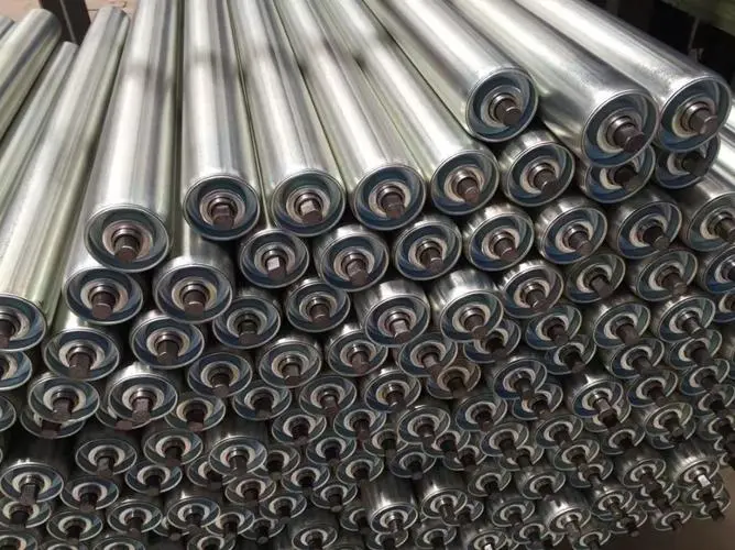
GRAM steel rollers show cylindrical bodies with bearing ends and projecting shaft interfaces. Those general roller details help explain why a visible body is only part of an assembly. They are not proof that an ordinary carrying roller is suitable as a local conveyor guide.
The GRAM nylon roller route is relevant when the actual specified body material is nylon. Keep the material declaration attached to the offered guide where it is proposed. A general nylon family description should not be converted into an unsupported grade, contact limit or complete guide rating.
For a distributor, identify whether the customer accepts a material alternative or requires the original declared material. Do not treat a change from steel to nylon as an unnoticed substitute. The customer’s accepted local contact and mounting requirements remain part of the decision.
Local guides and self-aligning idlers have different assembly scopes
GRAM self-aligning idlers show carrying support assemblies with frames and roller brackets. That is a different scope from a locally mounted guide. If the buyer compares those routes, compare them as distinct proposals for the actual observed conveyor condition.

The recurring belt-edge contact discussion addresses the underlying operating observation. This manufacturing enquiry focuses on defining the assembly selected after the relevant assessment. A precise guide drawing should not be presented as proof that the chosen guide solves every tracking cause.
Primary guide roller technical information separates working-body and mounting dimensions. That general drawing distinction is useful background. The listed models, bearings, threads and numerical dimensions are not GRAM specifications.
Mark retained guide parts and newly supplied parts explicitly
A proposed replacement can retain the surrounding bracket while changing the guide assembly. Identify both sides of that boundary. Where the supplier expects a particular mounting component, confirm whether it is retained or included in the actual offer.
GRAM’s conveyor accessories route provides a place to discuss associated components. It is not evidence that every bracket or fastener needed by a retained guide arrangement is supplied. Include only the actual agreed components in the purchasing scope.
Consider a contractor sending the same loose guide to two suppliers, one of whom quotes a complete assembly while the other excludes a mounting part. The prices address different scopes. Resolve the retained and supplied interfaces before presenting either as a complete replacement.
If a revised guide changes the mounting arrangement, record that as a revision instead of treating it as a body-only substitute. The project may need an additional interface assessment. A familiar working surface does not establish unchanged mounting requirements.
A distributor should preserve the same boundary in the customer description. If the supplied item does not include the support, say which retained support the proposal relies on. Do not expand a product photograph into an assumed installation package.
Manufacture against the guide drawing that the project accepted
Consider a contractor whose sketch shows the guide from the outside of the conveyor while the supplier interprets it from the belt side. A mounting feature can then appear on opposite sides even though both drawings use the same dimensions. Identify the viewing direction and current mounting relationship explicitly. A labelled arrangement reference prevents the manufacturer from having to choose between mirrored interpretations of an otherwise clear loose sample.
A vertical guide can create another sample problem when its mounting end is not distinguished from its free end. Keep the actual retained interface labelled in the enquiry rather than let the workshop photograph establish an accidental top or bottom. Where the offered construction changes the end arrangement, preserve that as a revision. The project should evaluate the actual proposed assembly in its intended orientation, without assuming that rotating the sample on a bench demonstrates suitability.
For several similar guides on one conveyor, preserve their local destinations alongside the accepted orientation references. A common body shape does not establish that their retained mounts are identical. Agree how the selected manufactured items will remain distinguishable in the actual delivery information.
Before release, identify the current drawing or construction reference, orientation, working contact and mounting basis. Where dimensions remain uncertain, keep that uncertainty visible. The manufacturer needs an identifiable proposal to produce rather than a collection of contradictory sample interpretations.
For a worn sample, distinguish observed dimensions from the nominal construction being accepted. The sample’s working surface may no longer represent the original profile. If the project chooses a revised offered shape, preserve the new reference rather than ask the manufacturer to reproduce the wear.
Agree delivery identification and protection for the actual working surface and mounting interfaces. The receiving information should connect the guide to its accepted orientation and destination. Do not assume an unpublished package method or use a similar body shape to establish the delivered item.
A guide enquiry is ready when the supplier can identify what rotates, what contacts the moving component and how the assembly is retained. Keep those relationships together in the accepted proposal so the manufactured guide represents the local arrangement the project actually selected.
Last Updated on October 3, 2026 by gramconveyor_admin


