
Impact Beds for Belt Conveyors Supplier Review: Where the Belt Enters and Leaves the Bed

The replacement impact bed may fit beneath the chute while leaving the belt poorly supported just before or after it. For a mine or aggregate plant retaining the surrounding idlers, the purchasing decision therefore extends beyond the bed’s overall dimensions. Review an impact beds for belt conveyors supplier offer as part of the belt’s route through the loading zone. GRAM’s load-zone belt support range is the starting point, with the approach supports, bed surfaces and departure supports shown together.
An impact beds for belt conveyors supplier should see the retained supports
A drawing of an isolated bed cannot show how the existing conveyor delivers the belt to its first support surface. Include the retained support immediately before the proposed assembly and the one immediately after it. Their relationship to the belt matters even when their mounting steel will not be changed during the retrofit.
A transfer contractor replacing a roller-supported section may receive an impact bed proposal that appears to occupy the available floor space. The contractor should also identify where the belt leaves the last retained roller, where contact with the proposed support begins, and where the belt returns to roller support. These are separate relationships within one installation, not dimensions that can be inferred from the bed length alone.
The last approach roller establishes the belt’s entry condition
GRAM’s steel roller range provides a recognizable support construction: a cylindrical working body, bearing ends and projecting shafts. Where an existing steel assembly is retained before the load zone, describe its installed support position and working relationship to the belt. The body diameter by itself does not specify that relationship.
If the approach roller is also being replaced, keep its new accepted drawing in the same interface review as the bed. A different supporting assembly may alter the proposed entry condition even if the replacement shaft fits the previous bracket. The bed supplier should assess the intended final arrangement, rather than a photograph taken before several changes were agreed.
The first departure support belongs on the same belt-path drawing
The belt does not stop being supported when it reaches the end of the bed. Identify how it passes to the first departure support and what remains fixed at that position. This allows the equipment review to address the supported belt path without treating the loading assembly as a self-contained section that can be approved independently of its neighbours.
The engineering team defines the actual permissible geometry. No universal support gap or transition dimension should be inferred from a general product image. GRAM’s proposal should show the interfaces to be approved, and the buyer should preserve the accepted values in the project documentation rather than filling missing dimensions with assumptions.
Belt conveyor impact beds combine longitudinal bars with a cross-belt shape
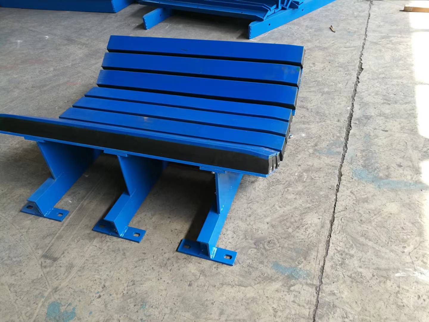
GRAM’s assembly photographs show longitudinal support bars carried by a fabricated frame, with central and inclined side support regions. These visible features help the buyer understand the form of the offered equipment. They do not establish a particular trough angle, a bar material specification or an allowable load for the actual order.
Along the conveyor: approach roller, supported loading section, departure roller.
Across the conveyor: centre support and the side support regions forming the agreed belt profile.
Both directions should be recognizable in the proposal. A lengthwise drawing may look continuous while omitting how the belt edges are supported. A cross-section may show a plausible trough while saying little about entry and exit. The buyer needs the relevant views together because the actual belt follows both relationships at the same time.
Central support bars do not describe the side support regions
When the order concerns a troughed belt, identify which pictured bars support the centre region and which support the inclined sides. Confirm the offered arrangement against the actual belt and retained supports. Calling every longitudinal element an impact bar is not a substitute for showing its position and function in the assembly.
A buyer retaining existing skirting should be particularly careful about that division. The proposed central support can look suitable while the relationship under the side regions remains unresolved. Keep the agreed supported belt profile visible in the proposal before the purchasing team treats the complete bed as ready for installation.

Mounting feet locate the frame, while the bars support the belt
The mounting feet visible in GRAM’s photographs are part of the frame’s installation relationship. The support bars define a different relationship with the belt. A proposal should make both clear, especially where the existing supporting steel is retained and the finished support position depends on the supplied frame arrangement.
This is why matching a footprint is not sufficient for approval. A frame may bolt into available space while its belt-contacting surfaces remain unsuitable for the intended route. The actual mounting and support dimensions require project acceptance; the buyer should not assume that a matching base automatically establishes the correct belt position.
At supply inspection, compare the delivered frame reference, mounting arrangement and assigned support bars with the same approved views. A substituted bar or frame component should be identified before it is accepted as equivalent. Where the proposal relies on different centre and side elements, keep their assignments clear so receiving personnel do not treat visually similar longitudinal parts as interchangeable.
This identification matters when separate loads deliver the frame and supporting elements. The order documentation should still connect each item to its position in the agreed profile, rather than relying on the arrangement seen in a promotional photograph.
Rubber-ring impact rollers remain a separate loading-zone option
GRAM’s impact rollers use rubber-ring working surfaces around rotating bodies. That construction is different from longitudinal support bars carried by a bed frame. If the inquiry allows either route, have the supplier identify which support arrangement is being offered and which adjacent roller interfaces remain in place.
A plant changing only a small part of its transfer zone should not assume that a bed and a ringed roller assembly are interchangeable packages. Their support surfaces, frame arrangements and proposed belt contact differ. The selection should follow the accepted loading-zone design and operating duty, with the retained equipment included in the review.
External manufacturers also treat load-zone support as an engineered system; Flexco’s support overview provides useful general context. Its proprietary features, bar constructions and rated duties belong to its products. They should not be transferred to a GRAM proposal or used to fill a missing specification.
The rubber belt must be identified before the bed profile is approved
The bed supports a particular belt, not an abstract outline. GRAM’s rubber conveyor belt range includes belt construction routes that require their own accepted specifications. Identify the belt intended to remain in service or the replacement construction planned for the project when reviewing the proposed support arrangement.
If the maintenance team changes the belt during the same shutdown, give the bed supplier the accepted replacement information. A support review based on the worn old belt may no longer describe the finished installation. Belt construction and supported shape should be assessed together by the responsible engineering team, rather than treated as independent purchasing substitutions.
A worn lower cover is not the original belt-contact specification
The surface presented by an old belt can help explain the operating history, but it should not silently become the dimensional basis for the new support. Separate the belt’s approved construction from its present worn condition. This distinction helps the supplier avoid confusing an observed maintenance problem with the intended geometry of the finished arrangement.
The same principle applies to a trial section or a site photograph. State what it represents and whether it matches the belt that will actually run over the delivered bed. Photographs are useful communication aids, but acceptance should refer to an identifiable belt and a defined support proposal.
Retained skirting and supplied support should have separate approval boundaries
A plant keeping its existing skirting may be tempted to treat the bed order as the only change at the transfer. Keep the supported belt profile and the retained skirting relationship visible in the engineering review. A bed proposal should not imply that every surrounding seal or chute part has also been assessed or included in supply.
GRAM’s conveyor accessories range provides additional component routes, but a category name does not define the delivered project package. Identify the bed frame, bars, mounting components and any separate roller assemblies in the accepted offer. Existing surrounding hardware should be identified as retained equipment unless its replacement is actually included.
For a multi-item delivery, preserve these distinctions on the component identification and receiving documents. The frame and its assigned support elements should remain traceable to the approved arrangement. Do not infer a packing method or an installation sequence from the way a product photograph groups its parts; agree those order details for the actual assembly.
Release the impact-bed order with entry and exit interfaces still visible
Service access is another part of the decision, covered separately in the impact-bed bar removal discussion. Resolve that access without losing the support-path review. A maintainable bed still needs the correct relationship to the belt and neighbouring idlers, just as a suitable support profile still needs an accepted service arrangement.
Before releasing the order, make sure the proposal can be read from the last approach support to the first departure support, with the agreed cross-belt profile identifiable between them. Where an interface is unresolved, keep it visible as an open engineering item. The useful purchase is the defined loading-zone arrangement that will be installed, not a bed whose isolated dimensions happen to fit the available space.
Last Updated on October 3, 2026 by gramconveyor_admin


